M15# MANUAL TRANSMISSION / TRANSAXLE MANUAL TRANSMISSION UNIT DISASSEMBLY
PROCEDURE

 46501
1.REMOVE PARKING BRAKE ASSEMBLY
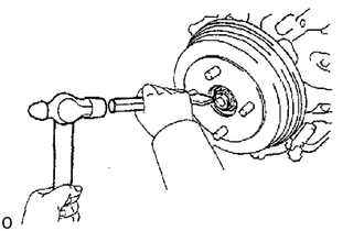
Using a chisel and hammer, unstake the lock nut.
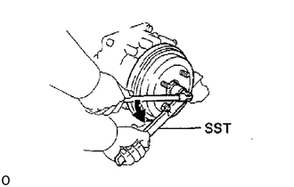
Using SST, remove the lock nut.
- SST
- 09330-00021
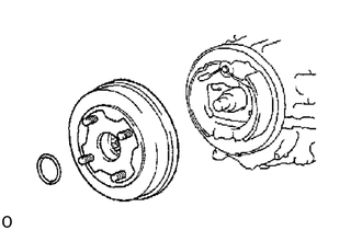
Remove the O-ring and brake drum.
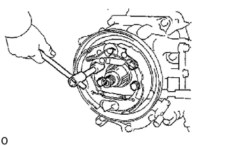
Remove the 4 bolts and parking brake assembly.
84210
2.REMOVE BACK-UP LIGHT SWITCH AND NEUTRAL SWITCH
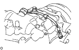
89411C
3.REMOVE SPEED SENSOR DRIVEN GEAR
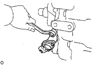
31204
4.REMOVE RELEASE FORK AND BEARING
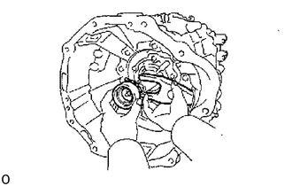
31111
5.REMOVE CLUTCH HOUSING FROM TRANSMISSION CASE
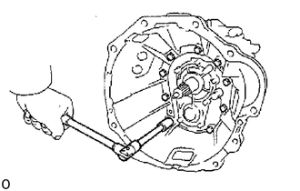
Remove the 9 bolts and the clutch housing.
33208
6.REMOVE SHIFT LEVER SHAFT HOUSING ASSEMBLY
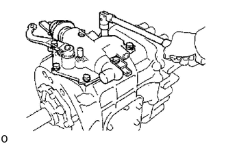
Remove the 7 bolts and wire clamp.
Using a plastic hammer, tap the shift lever shaft housing.
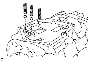
Using a magnetic finger, remove the 3 springs and balls.
33161B
7.REMOVE POWER TAKE-OFF COVER
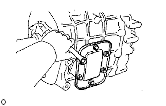
Remove the 6 bolts and power take-off cover with gasket.
33131
8.REMOVE FRONT BEARING RETAINER
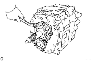
Remove the 7 bolts.
Using a plastic hammer, tap the front bearing retainer.
33151
9.REMOVE REAR BEARING RETAINER
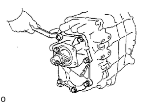
Remove the 8 bolts.
Using a plastic hammer, tap the rear bearing retainer.
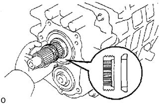
10.REMOVE SPEED SENSOR DRIVE GEAR AND SPACER
11.REMOVE TRANSMISSION FRONT CASE
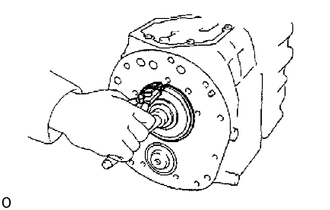
Using a snap ring expander, remove the snap ring from the input shaft bearing.
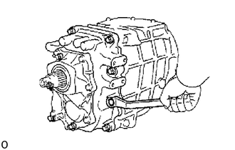
Remove the 9 bolts
Using a brass bar and hammer, carefully tap off the front case.
Remove the front case from the rear case.
33411A
12.REMOVE COUNTER FRONT BEARING FROM FRONT CASE
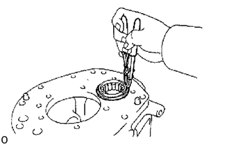
Using a snap ring expander, remove the snap ring.
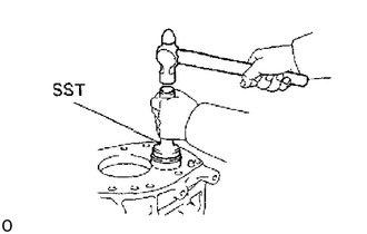
Using SST and a hammer, remove the bearing.
- SST
- 09505-20010
13.REMOVE 3 SET BOLTS
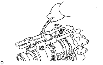
33213A
14.REMOVE SLOTTED SPRING PIN
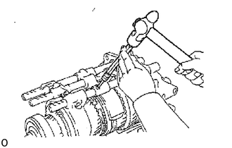
Using a pin punch and hammer, drive out the slotted spring pin from the shift head.
33213G
15.REMOVE NO. 2 SHIFT FORK SHAFT AND SHIFT FORK
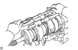
Pull out the No. 2 shift fork shaft from the rear case.
33266B
16.REMOVE NO. 1 INTERLOCK PIN
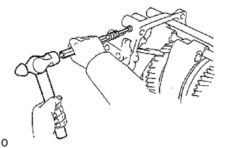
Using a pin punch and hammer, drive out the plug.
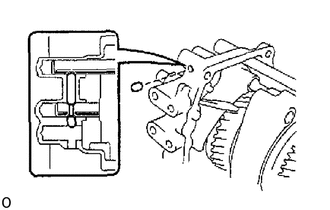
Using a magnetic finger, remove the No. 1 interlock pin from the rear case.
33205H
17.REMOVE NO. 1 SHIFT FORK SHAFT
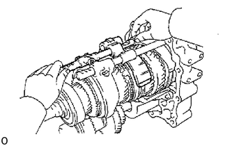
Pull out the No. 1 shift fork shaft from the rear case.
Using a magnetic finger, remove the No. 1 roller from the shaft hole.
Remove the No. 2 shift fork.
33265
18.REMOVE NO. 2 INTERLOCK PIN
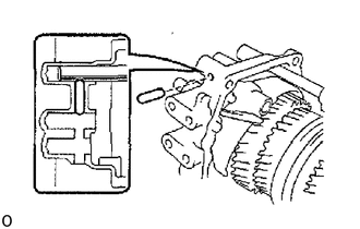
Using a magnetic finger, remove the No. 2 interlock pin from the rear case.
33244D
19.REMOVE NO. 3 SHIFT FORK SHAFT, SHIFT FORK AND SHIFT HEAD
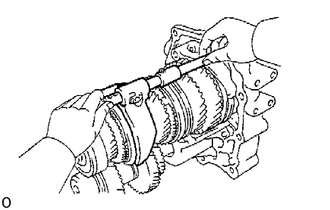
Pull out the No. 3 shift fork shaft from the rear case.
Remove the No. 3 shift fork and shift head.
33124C
20.REMOVE OIL RECEIVER
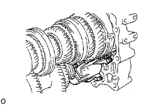
Remove the 3 bolts and oil receiver.
33411R
21.REMOVE SNAP RINGS
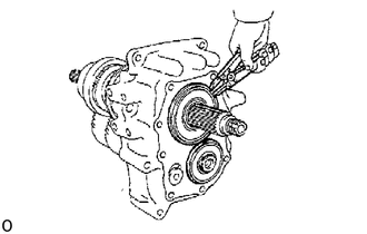
Using a snap ring expander, remove the 2 snap rings.
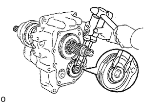
Using 2 screwdrivers and a hammer, tap out the snap ring.
33421
22.REMOVE COUNTER GEAR
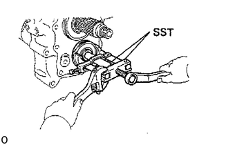
Using SST, remove the rear bearing.
- SST
- 09950-40011
Remove the counter gear.
33311
23.REMOVE INPUT AND OUTPUT SHAFTS
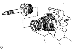
Remove the input shaft with the 10 needle roller bearings from the output shaft.
Remove the output shaft from the rear case by pulling on the output shaft and tapping on the rear case with a plastic hammer.
Remove the No. 1 shift fork.
24.INSPECT REVERSE IDLER GEAR THRUST CLEARANCE
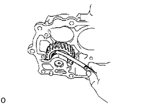
Using a feeler gauge, measure the reverse idler gear thrust clearance.
- Standard clearance:
0.1 to 0.5 mm (0.0039 to 0.0197 in.)
If the clearance more than the limit, replace the thrust washers.
33461
25.REMOVE REVERSE IDLER GEAR
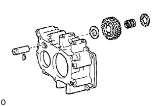
Pull out the shaft toward the rear and remove the key.
Remove the idler gear, needle roller bearing and thrust washers.
33124C
26.REMOVE OIL RECEIVER PIPE
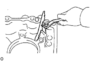
Remove the set bolt and oil receiver pipe from the rear case.
27.REMOVE MAGNET
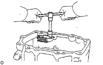
Remove the set bolt and magnet from the front case.