M15# MANUAL TRANSMISSION / TRANSAXLE MANUAL TRANSMISSION UNIT REASSEMBLY
CAUTION / NOTICE / HINT
- HINT:
-
Coat all of the sliding and rotating surface with gear oil before assembly.
PROCEDURE

 1.INSTALL MAGNET TO FRONT CASE
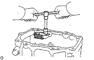
- Torque:
12 N*m (120 kgf*cm, 7 ft.*lbf)
33124C
2.INSTALL OIL RECEIVER PIPE TO REAR CASE
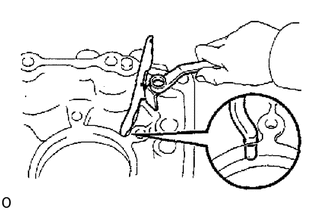
- Torque:
4.9 N*m (50 kgf*cm, 43 in.*lbf)
33461
3.INSTALL REVERSE IDLER GEAR AND SHAFT
Apply MP grease to the thrust washers.
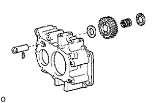
Install the reverse idler gear and thrust washers.
- HINT:
-
Be sure that protruding part of washer fits in the case groove.
- HINT:
-
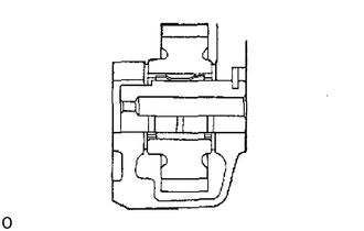
- ·
Make sure that the dimpled surface of both washers face the reverse idler gear.
·Make sure that the protruding part of the rear washer fits in the case groove.
Install the shaft with the woodruff key through the gear.
33321
4.INSTALL OUTPUT SHAFT TO REAR CASE
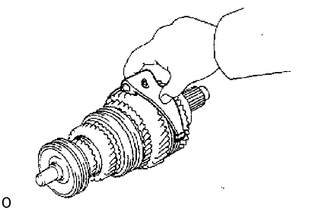
Place the No. 1 shift fork into the groove of No. 1 hub sleeve.
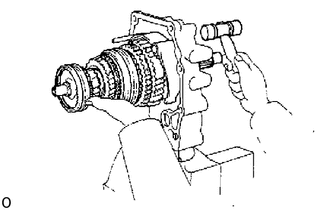
Install the output shaft into the rear case by pushing on the output shaft and tapping on the rear case.
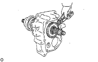
Using a snap ring expander, install the snap ring.
33311
5.INSTALL INPUT SHAFT
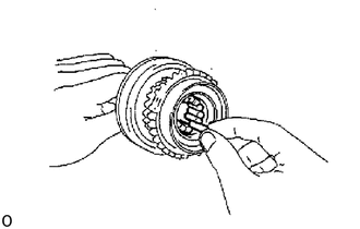
Apply MP grease to the 10 needle roller bearings and install them into the input shaft.
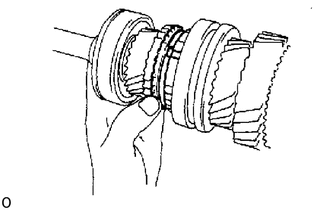
Install the input shaft to the output shaft with the synchronizer ring slots aligned with the shifting keys.
33421
6.INSTALL COUNTER GEAR
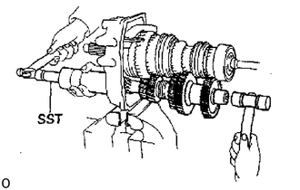
Install the counter gear into the rear case while holding the counter gear, and install the counter rear bearing with SST.
- SST
- 09316-60012 (09316-00011, 09316-00031)
- HINT:
-
When installing the rear bearing, support the counter gear in front with a 3-5 lb hammer or equivalent.
-
Ensure that the output shaft and counter gear do not strike against each other.
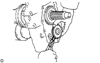
Using a snap ring expander, install the snap ring.
33411R
7.INSTALL SNAP RINGS
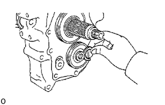
Select a snap ring that will allow minimum axial play.
| Mark | Thickness mm (in.) |
|---|---|
| 0 | 1.95-2.00 (0.0768-0.0787) |
| 1 | 2.00-2.05 (0.0787-0.0807) |
| 2 | 2.05-2.10 (0.0807-0.0827) |
| 3 | 2.10-2.15 (0.0827-0.0846) |
| 4 | 2.15-2.20 (0.0846-0.0866) |
| 5 | 2.20-2.25 (0.0866-0.0886) |
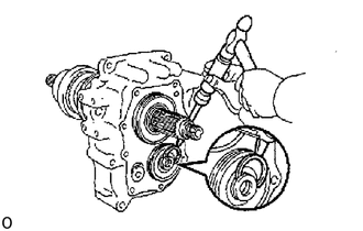
Using a screwdriver and hammer, install the snap ring.
33124C
8.INSTALL OIL RECEIVER
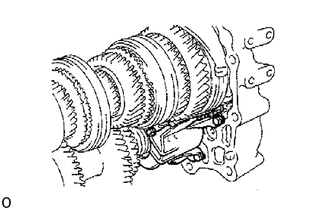
Install the oil receiver with the 3 bolts.
- Torque:
25 N*m (260 kgf*cm, 19 ft.*lbf)
33244D
9.INSTALL NO. 3 SHIFT FORK SHAFT, SHIFT FORK AND SHIFT HEAD
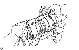
Place the No. 3 shift fork into the groove of the No. 3 hub sleeve.
Install the No. 3 shift fork shaft to the rear case through the No. 3 shift fork and shift head.
33265
10.INSTALL NO. 2 INTERLOCK PIN
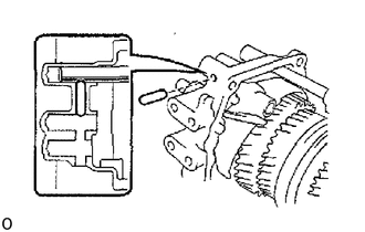
Apply MP grease to the No. 2 interlock pin.
Install the No. 2 interlock pin to the rear case.
33205H
11.INSTALL NO. 1 SHIFT FORK SHAFT
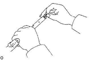
Apply MP grease to the No. 1 roller.
Install the No. 1 roller into the shaft hole.
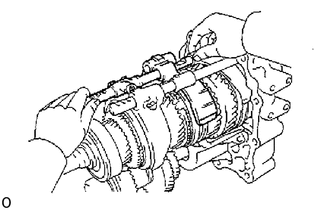
Install the No. 1 shift fork shaft to the rear case through the shift fork No. 1.
33266B
12.INSTALL NO. 1 INTERLOCK PIN
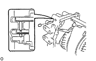
Apply MP grease to the No. 1 interlock pin.
Install the No. 1 interlock pin into the rear case.
33243A
13.INSTALL NO. 2 SHIFT FORK SHAFT AND SHIFT FORK
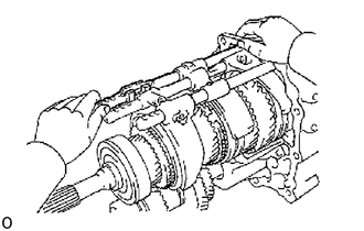
Place the No. 2 shift fork into the groove of No. 2 hub sleeve.
Install the No. 2 shift fork shaft to the rear case through the No. 2 shift fork.
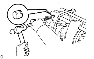
Apply seal packing to the hole plug, and install it to the rear case.
- Seal packing:
Part No. 08833-00070, THREE BOND 1324 or equivalent
- Drive in depth:
0.3 to 1.3 mm (0.012 to 0.051 in.)
Using a pin punch and hammer, drive in the hole plug to the rear case.
33232A
14.INSTALL SLOTTED SPRING PIN
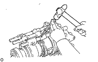
Using a pin punch and hammer, drive in the slotted spring pin to the shift head.
15.INSTALL SET BOLTS
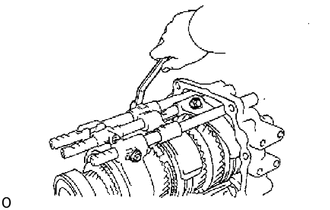
Install and torque the 3 bolts.
- Torque:
34 N*m (350 kgf*cm, 25 ft.*lbf)
16. CHECK INTERLOCK
Shift the No. 1 fork shaft to the 1st speed position.
No. 2 and No. 3 fork shafts should not move.
17.INSTALL SPEED SENSOR DRIVE GEAR AND SPACER
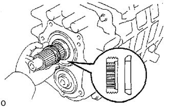
33151
18.INSTALL REAR BEARING RETAINER
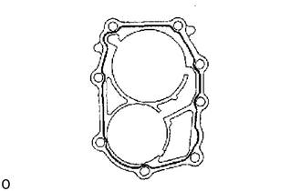
Apply seal packing to the retainer. as shown in the illustration and install it to the rear case.
- Seal packing:
Part No.08826-00090, THREE BONO 1281 or equivalent
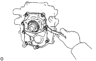
Apply seal packing to the bolts.
- Seal packing:
Part No.08833-00080, THREE BOND 1344, LOCTITE 242 or equivalent
Install and torque the 8 bolts.
- Torque:
34 N*m (350 kgf*cm, 25 ft.*lbf)
19.INSTALL TRANSMISSION FRONT CASE
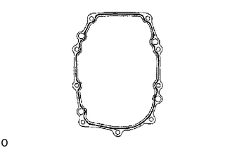
Apply seal packing to the front case, as shown in the illustration.
- Seal packing:
Part No. 08826-00090, THREE BOND 1281 or equivalent
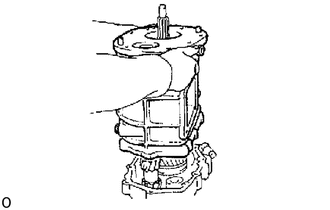
Align each bearing outer race and each fork shaft end with the case installation holes, and install the case.
If necessary, tap on the case with a plastic hammer.
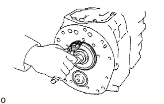
Using a snap ring expander, install the snap ring to the input shaft bearing.
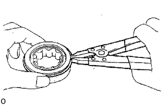
Using a snap ring expander, install the snap ring.
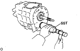
Using SST, drive in the counter front bearing.
- SST
- 09316-60012 (09316-00011)
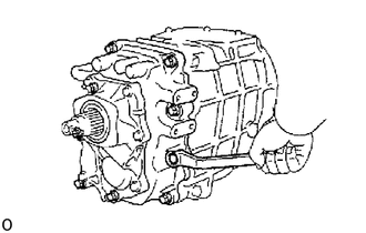
Install and torque the 9 bolts.
- Torque:
37 N*m (380 kgf*cm, 27 ft.*lbf)
33131
20.INSTALL FRONT BEARING RETAINER
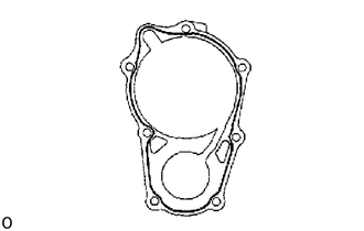
Apply seal packing to the retainer, as shown in the illustration, and install it to the front case.
- Seal packing:
Part No. 08826-00090, THREE BOND 1281 or equivalent
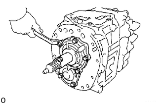
Apply seal packing to the bolts.
- Seal packing:
Part No.08833-00080, THREE BOND 1344, LOCTITE 242 or equivalent
Install and torque the 7 bolts.
- Torque:
17 N*m (170 kgf*cm, 12 ft.*lbf)
33208
21.INSTALL SHIFT LEVER SHAFT HOUSING ASSEMBLY
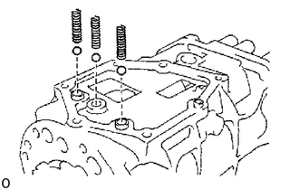
Install the 3 balls and springs
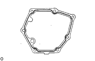
Apply seal packing to the housing. as shown in the illustration, and install it to the front case
- Seal packing:
Part No. 08826-00090, THREE BOND 1281 or equivalent
- HINT:
-
Insure that the tip of No. 2 shift lever is positioned securely in the shift head.
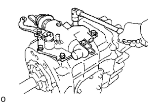
Apply seal packing to the bolts.
- Seal packing:
Part No.08833-00080, THREE BOND 1344, LOCTITE 242 or equivalent
Install and torque the 7 bolts.
- Torque:
17 N*m (170 kgf*cm, 12 ft.*lbf)
33161
22.INSTALL POWER TAKE-OFF COVER WITH GASKET
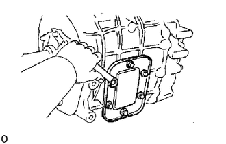
Apply seal packing to the bolts.
- Seal packing:
Part No.08833-00080, THREE BOND 1344, LOCTITE 242 or equivalent
Install and torque the 6 bolts.
- Torque:
14 N*m (145 kgf*cm, 11 ft.*lbf)
33208
23. AFTER INSTALLING SHIFT LEVER SHAFT HOUSING, CHECK FOLLOWING ITEMS:
Check to see that the input and output shafts rotate smoothly.
Check to see that shifting is smooth to all positions.
31111
24.INSTALL CLUTCH HOUSING
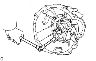
Install the clutch housing.
Install and torque the bolts.
- Torque:
37 N*m (380 kgf*cm, 27 ft.*lbf)
31236B
25.INSTALL RELEASE FORK AND BEARING
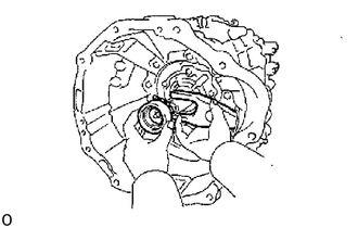
Apply molybdenum disulphide lithium base grease to following parts:
Release bearing hub inside groove
Input shaft spline
Release fork contact surface
Apply MP grease to the release bearing front.
89411C
26.INSTALL SPEED SENSOR DRIVEN GEAR
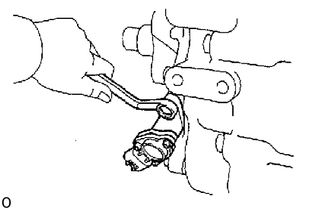
- Torque:
11 N*m (115 kgf*cm, 8 ft.*lbf)
84210
27.INSTALL BACK-UP LIGHT SWITCH, NEUTRAL SWITCH
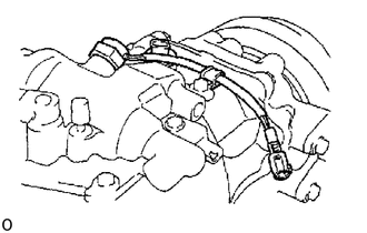
Back-up light switch
- Torque:
44 N*m (450 kgf*cm, 33 ft.*lbf)
Neutral switch
- Torque:
39 N*m (400 kgf*cm, 29 ft.*lbf)
46501
28.INSTALL PARKING BRAKE ASSEMBLY
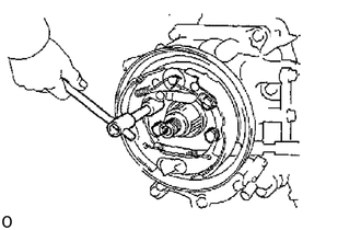
Install the parking brake assembly to the rear bearing retainer.
Apply seal packing to the bolts.
- Seal packing:
Part No.08833-00080, THREE BOND 1344, LOCTITE 242 or equivalent
Install and torque the 4 bolts.
- Torque:
47 N*m (475 kgf*cm, 34 ft.*lbf)
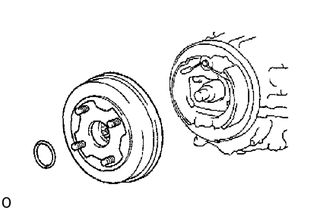
Install the brake drum and a new O-ring.
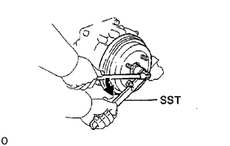
Using SST, install and torque the lock nut.
- SST
- 09330-00021
- Torque:
127 N*m (1.300 kgf*cm, 94 ft.*lbf)
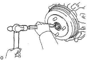
Using a pin punch and hammer, stake the lock nut.