M15# MANUAL TRANSMISSION / TRANSAXLE OUTPUT SHAFT REASSEMBLY
CAUTION / NOTICE / HINT
- HINT:
-
Coat all of the sliding and rotating surface with gear oil before assembly.
PROCEDURE

 33363
1.INSTALL NO. 1, NO. 2 AND NO. 3 CLUTCH HUBS INTO HUB SLEEVES
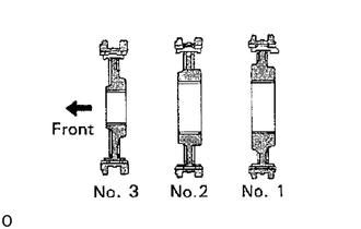
Install the clutch hub and shifting keys to the hub sleeve.
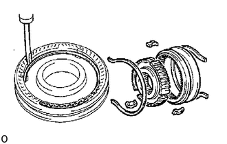
Install the shifting key springs under the shifting keys.
- NOTICE:
-
Install the key springs positioned so that their end gaps are not in line.
33364
2.INSTALL 2ND GEAR AND NO. 2 HUB SLEEVE
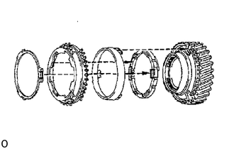
Apply gear oil to the shaft and needle roller bearing.
Place the synchronizer rings on the gear and align the ring slots with the shifting keys.
- NOTICE:
-
-
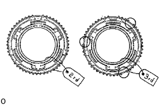
The outer synchronizer ring for 3rd gear has 1 tooth less in each group of driven teeth than on 2nd gear.
-
Make sure that the correct synchronizer ring is installed for the gear.
Install the 2nd gear needle roller bearing.
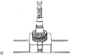
Using a press, install the 2nd gear and No. 2 hub sleeve.
3.INSTALL SNAP RING
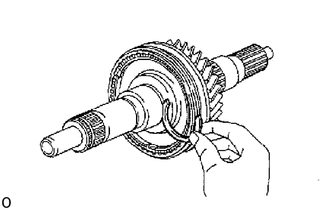
Select a snap ring that will allow minimum axial play.
| Mark | Thickness mm (in.) |
|---|---|
| 2 | 1.90-1.95 (0.0748-0.0768) |
| 3 | 1.95-2.00 (0.0768-0.0787) |
| 4 | 2.00-2.05 (0.0787-0.0807) |
| 5 | 2.05-2.10 (0.0807-0.0827) |
| 6 | 2.10-2.15 (0.0827-0.0846) |
| 7 | 2.15-2.20 (0.0846-0.0866) |
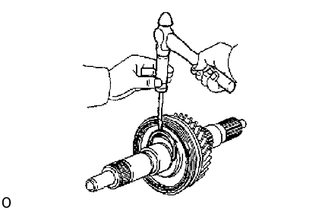
Using a screwdriver and hammer, install the snap ring.
4.INSPECT 2ND GEAR THRUST CLEARANCE
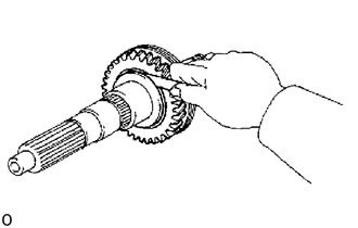
Using a feeler gauge, measure the 2nd gear thrust clearance.
- Standard clearance:
0.1 to 0.35 mm (0.0039 to 0.0138 in.)
33333
5.INSTALL 3RD GEAR AND THRUST WASHER
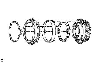
Apply gear oil to the needle roller bearing.
Assemble the 3rd gear, synchronizer rings and needle roller bearing.
- NOTICE:
-
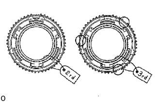
-
The outer synchronizer ring for 3rd gear has 1 tooth less in each group of driven teeth than on 2nd gear.
-
Make sure that the correct synchronizer ring is installed for the gear.
Install the assembly on the shaft with the synchronizer ring slots aligned with the shifting keys.
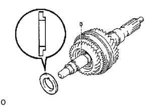
Install the thrust washer onto the output shaft with the straight pin aligned with the thrust washer.
6.INSTALL SNAP RING
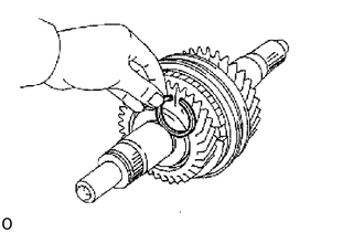
Select a snap ring that will allow minimum axial play.
| Mark | Thickness mm (in.) |
|---|---|
| A | 2.90-2.95 (0.1142-0.1161) |
| B | 2.95-3.00 (0.1161-0.1181) |
| C | 3.00-3.05 (0.1181-0.1201) |
| D | 3.05-3.10 (0.1201-0.1220) |
| F | 3.10-3.15 (0.1220-0.1240) |
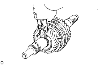
Using a snap ring expander, install the snap ring.
7.INSPECT 3RD GEAR THRUST CLEARANCE
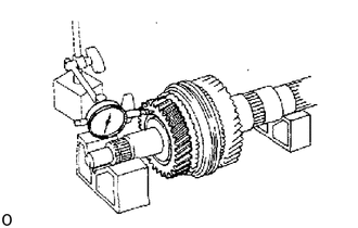
Using a dial indicator, measure the 3rd gear thrust clearance.
- Standard clearance:
0.10 to 0.60 mm (0.0039 to 0.0236 in.)
33336
8.INSTALL 5TH GEAR AND NO. 3 HUB SLEEVE
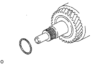
Install the spacer on the output shaft.
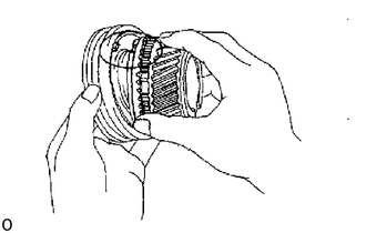
Apply gear oil to the needle roller bearing.
Place the synchronizer ring on the gear and align the ring slots with the shifting keys.
Install the needle roller bearing in the 5th gear.
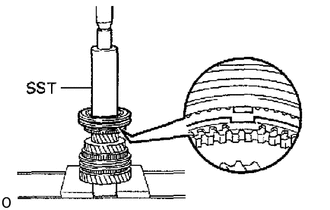
Using SST and a press, install the 5th gear and No. 3 hub sleeve.
- SST
- 09316-60012 (09316-00011)
9.INSTALL SNAP RING
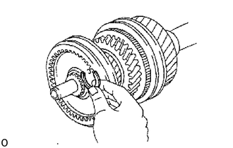
Select a snap ring that will allow minimum axial play.
| Mark | Thickness mm (in.) |
|---|---|
| 4 | 1.90-1.95 (0.0748-0.0768) |
| 5 | 1.95-2.00 (0.0768-0.0787) |
| 6 | 2.00-2.05 (0.0787-0.0807) |
| 7 | 2.05-2.10 (0.0807-0.0827) |
| 8 | 2.10-2.15 (0.0827-0.0846) |
| 9 | 2.15-2.20 (0.0846-0.0866) |
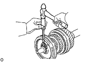
Using a screwdriver and hammer, install the snap ring.
10.INSPECT 5TH GEAR THRUST CLEARANCE
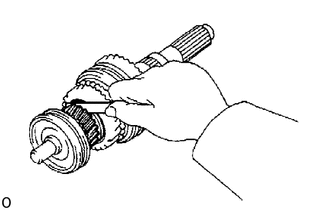
Using a feeler gauge, measure the 5th gear thrust clearance.
- Standard clearance:
0.10 to 0.50 mm (0.0039 to 0.0197 in.)
33335
11.INSTALL 1ST GEAR AND NO. 1 HUB SLEEVE
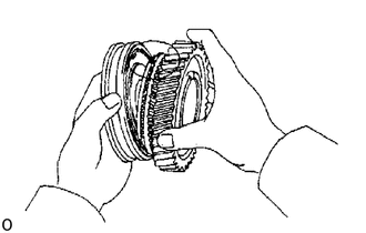
Apply gear oil to the shaft and needle roller bearing.
Place the synchronizer ring on the gear and align the ring slots with the shifting keys.
Install the 1st gear needle roller bearing.
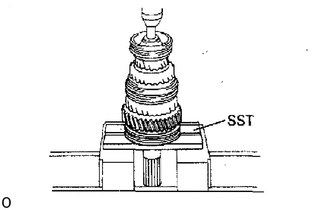
Using SST and a press, install the 1st gear and No. 1 hub sleeve.
- SST
- 09527-30010
12.INSPECT 1ST GEAR THRUST CLEARANCE
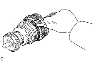
Using a feeler gauge, measure the 1st gear thrust clearance.
- Standard clearance:
0.10 to 0.35 mm (0.0039 to 0.0138 in.)
33331
13.INSTALL REVERSE GEAR
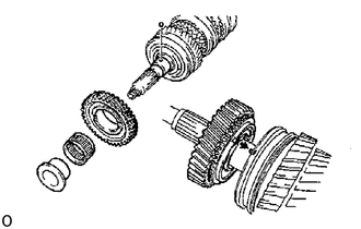
Apply gear oil to the needle roller bearing.
Install the ball on the output shaft.
Install the reverse gear's needle roller bearing and inner race.
Install the reverse gear onto the output shaft with the ball aligned with the inner race.
33321A
14.INSTALL OUTPUT SHAFT REAR BEARING
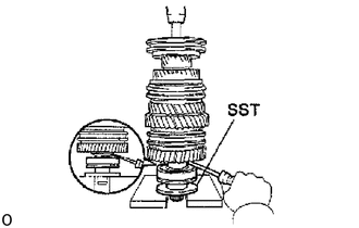
Using SST and a press, install the bearing on the shaft with the outer race snap ring groove toward the rear.
- HINT:
-
Hold the reverse gear and thrust washer with a screwdriver to prevent it from falling.
- SST
- 09316-60012 (09316-00041)
15.INSTALL REVERSE GEAR THRUST CLEARANCE
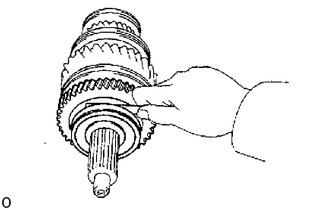
Using a feeler gauge, measure the reverse gear thrust clearance.
- Standard clearance:
0.15 to 0.40 mm (0.0059 to 0.0157 in.)