M551 MANUAL TRANSMISSION / TRANSAXLE SHIFT AND SELECT TRANSMISSION CONTROL CABLE INSTALLATION
PROCEDURE

 1.INSTALL SHIFT AND SELECT TRANSMISSION CONTROL CABLE
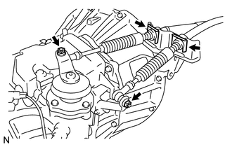
Install the shift and select transmission control cable with the 2 nuts.
- Torque:
15 N*m (153 kgf*cm, 11 ft.*lbf)
Install 2 new clips onto the transmission control cable bracket.
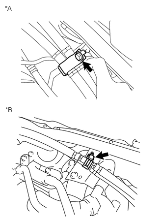
Install the No. 4 transmission control cable bracket with the bolt.
- Torque:
12 N*m (122 kgf*cm, 9 ft.*lbf)
| *A | for RHD |
| *B | for LHD |
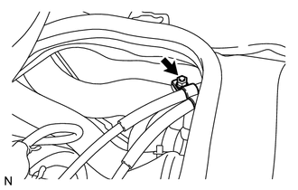
for LHD:
Install the transmission control cable clamp with the nut.
- Torque:
12 N*m (122 kgf*cm, 9 ft.*lbf)
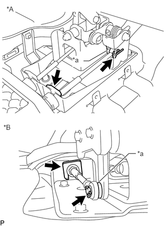
Connect the select transmission control cable to the selecting bell crank and install a new clip and washer.
| *A | for RHD |
| *B | for LHD |
| *a | Selection Bell Crank |
Connect the select transmission control cable to the floor shift control shift lever retainer and install a new clip.
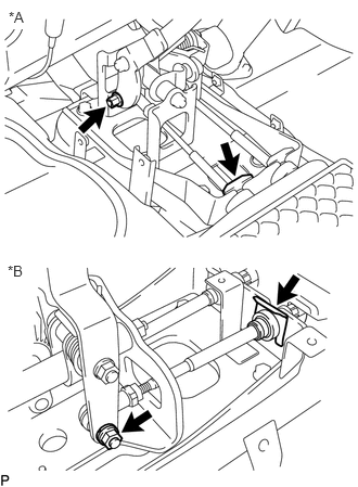
Connect the shift transmission control cable to the floor shift shift lever sub-assembly with the nut.
- Torque:
15 N*m (153 kgf*cm, 11 ft.*lbf)
| *A | for RHD |
| *B | for LHD |
Connect the shift transmission control cable to the floor shift control shift lever retainer and install a new clip.
58410
2.INSTALL ENGINE SERVICE HOLE COVER
58420
3.INSTALL NO. 2 ENGINE SERVICE HOLE COVER ASSEMBLY
58521D
4.INSTALL ENGINE SERVICE HOLE COVER MAT
58848A
5.INSTALL SHIFT LEVER HOLE COVER
Install the shift lever hole cover with the 4 bolts.
33555D
6.INSTALL SHIFT LEVER BOOT
for RHD:
Install the shift lever boot with the 3 bolts.
for LHD:
Install the shift lever boot with the 4 bolts.
58534A
7.INSTALL TRANSMISSION COVER MAT
Install the transmission cover mat to the shift and select lever support.
33504F
8.INSTALL SHIFT LEVER KNOB SUB-ASSEMBLY
Gently rotate the shift lever knob sub-assembly by hand until it locks.
After locking, further tighten by 1.5 turns.
After tightening, rotate and adjust the tightened direction so that the shift pattern is positioned within +/-10° of the front of the vehicle.
33820B
9.ADJUST TRANSMISSION CONTROL CABLE ASSEMBLY
Insert the cable into the shift lever when the shift lever is in the neutral position at the distance specified in the illustration.
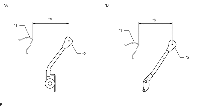
| *A | for LHD | *B | for RHD |
| *1 | Instrument Panel | *2 | Shift Lever Knob Sub-assembly |
| *a | 236.7 mm (9.32 in.) | *b | 220.9 mm (8.70 in.) |
- Standard Distance:
- for RHD:
220.9 mm (8.70 in.)
- for LHD:
236.7 mm (9.32 in.)
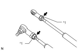
If the length of the cable needs adjustment, loosen the lock nut and adjust the length by turning the ball joint.
| *1 | Lock Nut |
Tighten the lock nut after adjusting it.
- Torque:
12 N*m (122 kgf*cm, 9 ft.*lbf)
33820B
10.INSPECT TRANSMISSION CONTROL CABLE ASSEMBLY
Confirm that the distance between the shift knob and the instrument panel is as specified when the shift lever is in the neutral position.
Check that the shift lever can be smoothly moved into each shift position.
Check that the shift lever can be operated smoothly when the shift lever is engaged.
Check that the shift lever smoothly returns to the neutral position when selecting it.
Check that no abnormal sounds occur while operating the shift lever.