M551 MANUAL TRANSMISSION / TRANSAXLE MANUAL TRANSMISSION UNIT DISASSEMBLY
CAUTION / NOTICE / HINT
- NOTICE:
-
When working with FIPG (seal packing) material, you must observe the following items.
- ·
Using a razor blade and gasket scraper, remove all old FIPG material from the gasket surfaces.
·Thoroughly clean all components.
·Clean both sealing surfaces with non-residue solvent.
·Apply FIPG to an approximately 1.2 mm (0.047 in.) wide bead of FIPG material along the sealing surface.
·Parts must be assembled within 10 minutes after application of FIPG material. Otherwise, the FIPG material must be removed and reapplied.
PROCEDURE

 1.REMOVE BACK-UP LIGHT SWITCH ASSEMBLY
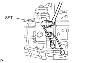
Using SST, remove the switch and gasket.
- SST
- 09817-16011
84540C
2.REMOVE EXHAUST BRAKE NEUTRAL SWITCH ASSEMBLY
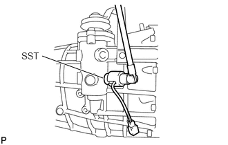
Using SST, remove the switch and gasket.
- SST
- 09817-16011
33101A
3.REMOVE MANUAL TRANSMISSION FILLER PLUG
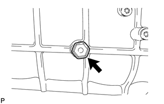
Remove the filler plug and gasket.
4.REMOVE DRAIN PLUG SUB-ASSEMBLY
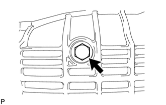
Remove the drain plug and gasket.
33161
5.REMOVE MANUAL TRANSMISSION POWER TAKE-OFF COVER
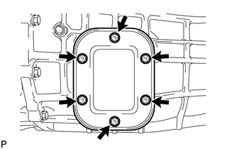
Remove the 6 bolts, cover and gasket.
6.REMOVE SPEEDOMETER DRIVEN GEAR SUB-ASSEMBLY
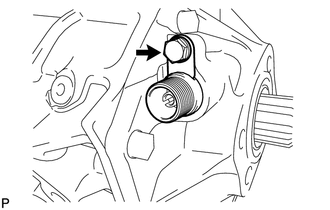
Remove the bolt, lock plate and driven gear.
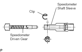
Remove the clip from the speedometer sleeve.
Remove the driven gear from the sleeve.
Remove the O-ring from the sleeve.
Check the teeth of the speedometer driven gear.If the driven gear is damaged, replace it.
7.REMOVE OUTPUT SHAFT REAR BEARING RETAINER
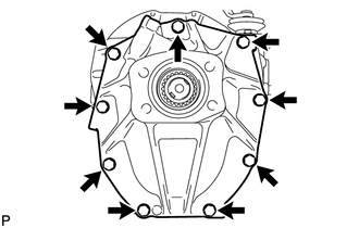
Remove the 9 bolts.
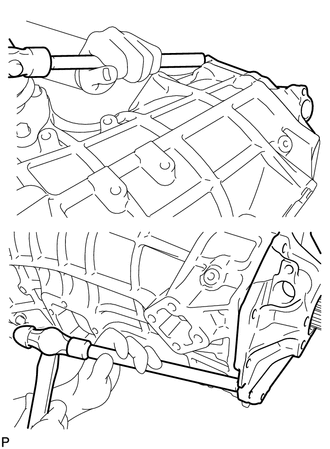
Using a brass bar and hammer, carefully tap out the bearing retainer.
- HINT:
-
Make the brass bar touched the rib portion of the case.
33141A
8.REMOVE TRANSMISSION REAR BEARING RETAINER OIL SEAL
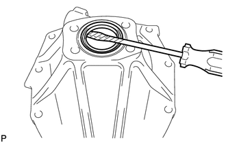
Using a screwdriver, pry out the oil seal.
- HINT:
-
Tape the screwdriver tip before use.
35469P
9.REMOVE TRANSMISSION REAR RETAINER SPACER
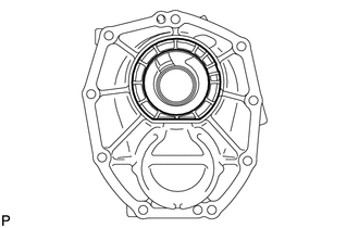
Remove the transmission rear retainer spacer from the output shaft rear bearing retainer.
10.REMOVE SPEEDOMETER DRIVE GEAR
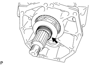
Remove the speedometer drive gear from the output shaft.
33124L
11.REMOVE NO. 3 OIL RECEIVER PIPE
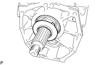
Remove the No. 3 oil receiver pipe from the output shaft.
12.REMOVE SPEEDOMETER DRIVE GEAR PIN
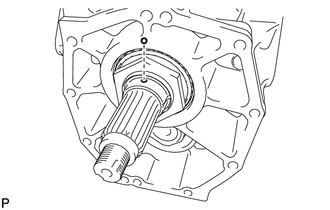
Remove the speedometer drive gear pin from the output shaft.
33421D
13.REMOVE COUNTER GEAR REAR NUT
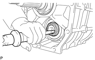
Using a chisel and hammer, unstake the lock nut.
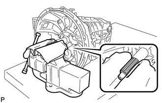
Fix the input shaft's spline part through 2 protective aluminum plates and a shop rag in a vise, and move the gear to the 4th place.
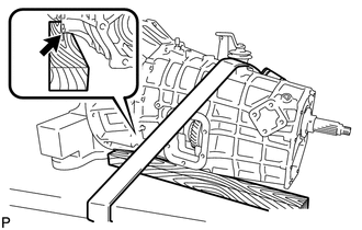
Using 2 belts and a wooden block, fasten the transmission to the work bench.
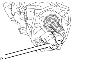
Using a 50 mm socket wrench, remove the lock nut from the counter gear.
14.REMOVE OUTPUT SHAFT ADJUSTING NUT
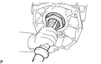
Using a chisel and hammer, unstake the nut.
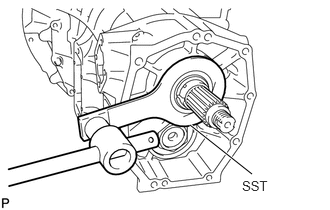
Using SST, remove the nut from the output shaft.
- SST
- 09922-10010
Remove the 2 belts and wooden block from the transmission.
Move the gear back to neutral and remove the input shaft spline part from the vise.
33257
15.REMOVE SELECT OUTER LEVER
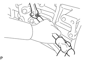
Remove the nut and spring washer from the select lever shaft knock pin.
Install the nut to the select lever shaft knock pin.
Using a brass bar and hammer, tap the nut and disengage the knock pin from the outer select lever.
- NOTICE:
-
Do not directly tap the knock pin.
Remove the select lever from the select lever shaft.
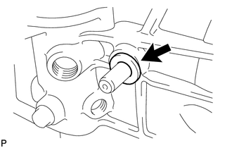
Remove the washer from the select lever shaft.
16.REMOVE SHIFT LEVER SHAFT HOUSING
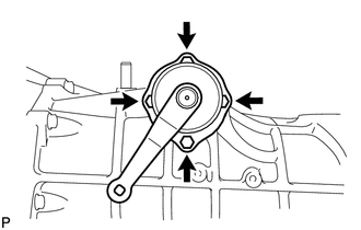
Remove the 4 bolts, shift housing and select return spring from the transmission case.
33451H
17.REMOVE REVERSE IDLER GEAR SHAFT BOLT
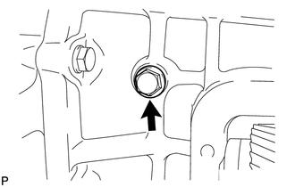
Remove the reverse idler gear shaft bolt from the reverse idler gear shaft.
18.REMOVE SHIFT DETENT BALL
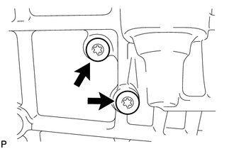
Using a "TORX" wrench (T40), remove the 2 plugs.
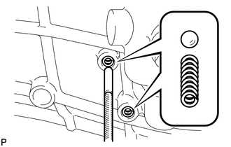
Using a magnet finger, remove the 2 springs and 2 shift detent balls.
33101
19.REMOVE MANUAL TRANSMISSION CASE SUB-ASSEMBLY
Remove the 12 bolts.
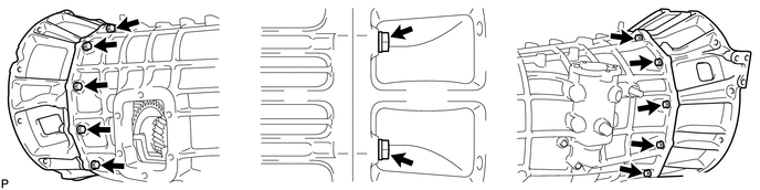
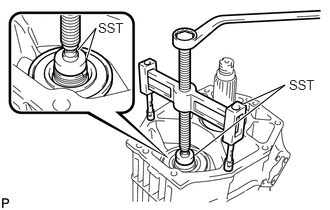
Using SST, remove the counter gear rear bearing, output shaft spacer and transmission case from the clutch housing.
- SST
- 09950-40011 (09951-04020, 09953-04030, 09957-04010)
09950-50013 (09952-05010, 09954-05021, 09955-05010)
09950-60011 (09951-00330)
33124C
20.REMOVE NO. 1 OIL RECEIVER PIPE
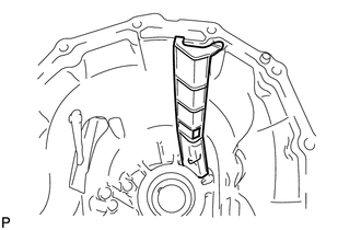
Remove the No. 1 oil receiver pipe from the transmission case.
33205
21.REMOVE SELECT LEVER SHAFT SUB-ASSEMBLY
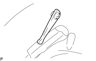
Remove the select lever shaft from the transmission case.
33126
22.REMOVE OIL RECEIVER SEAL
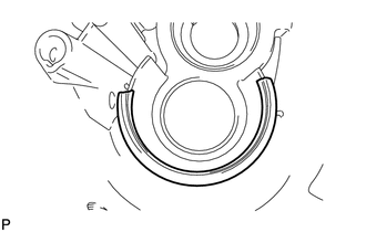
Remove the oil receiver seal from the transmission case.
23.REMOVE NO. 2 SHIFT LEVER SHAFT OIL SEAL
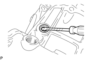
Using a screwdriver, pry out the oil seal from the transmission case.
- HINT:
-
Tape the screwdriver tip before use.
24.REMOVE TRANSMISSION OIL SEPARATOR
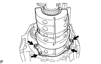
Remove the 4 bolts and oil separator.
33124D
25.REMOVE NO. 2 OIL RECEIVER PIPE
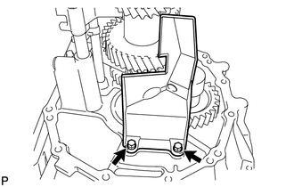
Remove the 2 bolts and oil receiver.
26.INSPECT REVERSE IDLER GEAR THRUST CLEARANCE
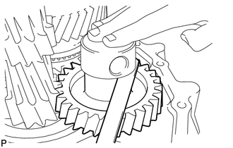
Using a feeler gauge, measure the thrust clearance.
- Standard clearance:
0.10 to 0.62 mm (0.0039 to 0.0242 in.)
- Maximum clearance:
0.62 mm (0.0242 in.)
27.INSPECT REVERSE IDLER GEAR RADIAL CLEARANCE
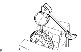
Using a dial indicator, measure the radial clearance.
- Standard clearance:
0.015 to 0.059 mm (0.0006 to 0.0023 in.)
- Maximum clearance:
0.059 mm (0.0023 in.)
If the clearance is not as specified, replace the reverse idler gear needle roller bearing.
33461
28.REMOVE REVERSE IDLER GEAR
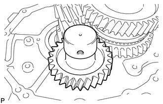
Remove the gear shaft, needle roller bearing and gear.
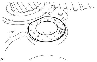
Remove the idler gear thrust washer.
33321A
29.REMOVE OUTPUT SHAFT REAR BEARING
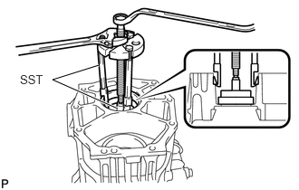
Using SST, remove the roller bearing from the transmission case.
- SST
- 09950-30012 (09951-03010, 09953-03010, 09954-03010, 09955-03021)
09950-40011 (09957-04010)
09950-60021 (09951-00750, 09952-06010)
33321V
30.REMOVE OUTPUT SHAFT CENTER BEARING
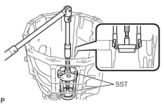
Using SST, remove the roller bearing from the transmission case.
- SST
- 09950-30012 (09951-03010, 09953-03010, 09954-03010, 09955-03021)
09950-40011 (09957-04010)
09950-60011 (09951-00590, 09951-00610, 09952-06010)
33240
31.REMOVE REVERSE SHIFT ARM BRACKET ASSEMBLY
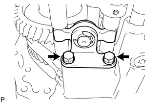
Remove the 2 bolts and reverse shift arm bracket assembly from the clutch housing.
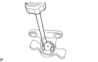
Using a screwdriver, remove the E-ring, shift lever and pin from the shift lever inner mount.
33275B
32.REMOVE SHAFT DETENT BALL
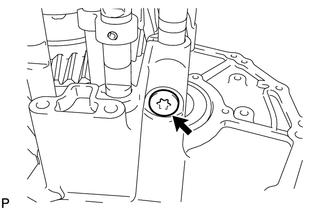
Using a "TORX" socket wrench (T40), remove the shift detent ball plug from the clutch housing.
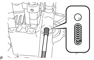
Using a magnetic finger, remove the spring and ball from the clutch housing.
33244D
33.REMOVE NO. 3 GEAR SHIFT FORK SHAFT
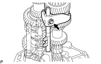
Remove the bolt, shift fork shaft and gear shift fork.
33245G
34.REMOVE NO. 4 GEAR SHIFT FORK SHAFT
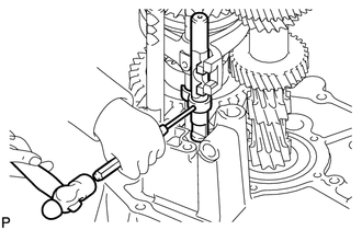
Using a pin punch (5 mm (0.20 in.)) and hammer, tap out the shift fork slotted pin from the shift fork shaft and gear shift fork guide.
33242
35.REMOVE NO. 1 GEAR SHIFT FORK SHAFT
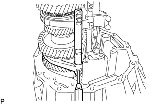
Using a pin punch (5 mm (0.20 in.)) and hammer, tap out the slotted pin from the shift fork shaft and gear shift fork.
33243A
36.REMOVE NO. 2 GEAR SHIFT FORK SHAFT
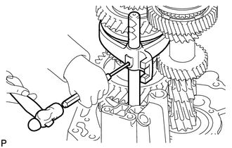
Using a pin punch (5 mm (0.20 in.)) and hammer, tap out the slotted pin from the shift fork shaft and gear shift fork.
33321
37.REMOVE OUTPUT SHAFT
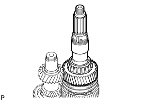
Remove the output shaft and No. 4 synchronizer ring.
31111
38.FIX CLUTCH HOUSING
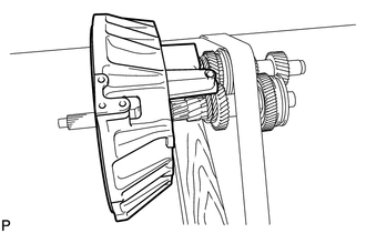
Bind the input shaft and counter gear together with a rope or wire.
Place them on a wooden block and fix them to the work bench with a belt.
- NOTICE:
-
Be careful not to drop the clutch housing assembly.
33131
39.REMOVE FRONT BEARING RETAINER
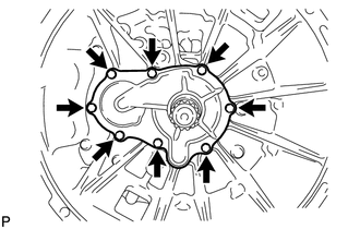
Remove the 8 bolts and retainer.
33131A
40.REMOVE TRANSMISSION FRONT BEARING RETAINER OIL SEAL
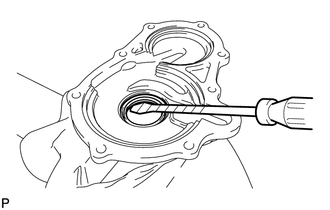
Using a screwdriver, pry out the oil seal from the retainer.
- HINT:
-
Tape the screwdriver tip before use.
33124M
41.REMOVE NO. 4 OIL RECEIVER PIPE
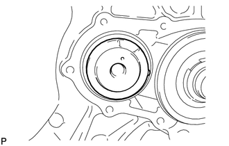
Remove the oil receiver from the clutch housing.
33311G
42.REMOVE FRONT BEARING SHAFT SNAP RING
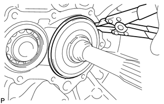
Using a snap ring expander, remove the snap ring from the input shaft front bearing.
43.REMOVE COUNTER GEAR FRONT BEARING SNAP RING
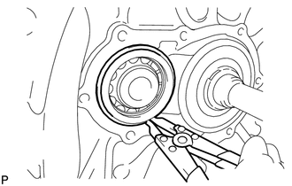
Using a snap ring expander, remove the snap ring from the counter gear front bearing.
31111
44.REMOVE CLUTCH HOUSING
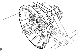
Using a plastic hammer, tap out the clutch housing.
- NOTICE:
-
Do not allow the clutch housing assembly to fall.
Remove the rope or wire from the input shaft and counter gear.
45.REMOVE COUNTER GEAR FRONT BEARING
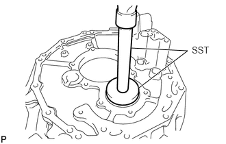
Using SST and a hammer, remove the bearing from the clutch housing.
- SST
- 09950-70010 (09951-07100)
09950-60021 (09951-00680)
33461
46.INSPECT REVERSE IDLER GEAR
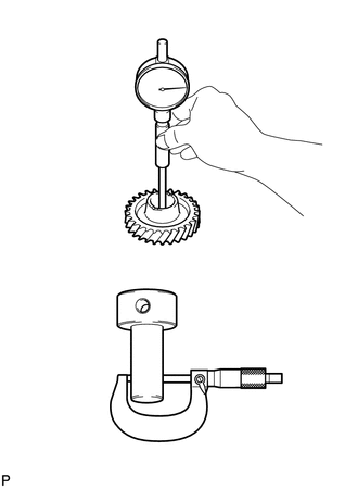
Using a cylinder gauge, measure the inside diameter of the gear.
- Standard inside diameter:
35.015 to 35.036 mm (1.3785 to 1.3793 in.)
- Maximum inside diameter:
35.036 mm (1.3793 in.)
If the inside diameter exceeds the maximum, replace the reverse idler gear.
Using a micrometer, measure the outer diameter of the idler gear shaft.
- Standard outer diameter:
27.987 to 28.000 mm (1.1018 to 1.1024 in.)
- Minimum outer diameter:
27.987 mm (1.1018 in.)
If the diameter is less than the minimum, replace the reverse idler gear shaft.