M551 MANUAL TRANSMISSION / TRANSAXLE MANUAL TRANSMISSION UNIT REASSEMBLY
PROCEDURE

 1.INSTALL COUNTER GEAR FRONT BEARING
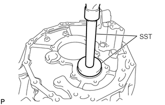
Using SST and a hammer, tap in a new bearing to the clutch housing.
- SST
- 09950-70010 (09951-07100)
09950-60021 (09951-00680)
- NOTICE:
-
When installing, face the snap ring grooves to the engine side.
31111
2.INSTALL CLUTCH HOUSING
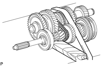
Bind the input shaft and counter gear together with a rope or wire.
Place them on a wooden block and fix them to the work bench with a belt.
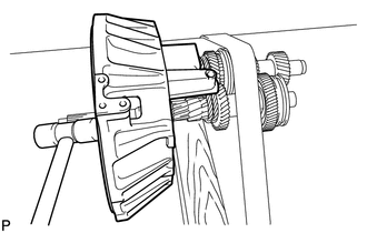
Using a plastic hammer, tap in the input shaft and counter gear.
- NOTICE:
- ·
Do not allow the clutch housing to fall.
·Be careful not to damage or drop the counter gear front bearing.
33311G
3.INSTALL FRONT BEARING SHAFT SNAP RING
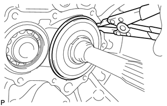
Using a snap ring expander, install a new snap ring to the input shaft front bearing.
4.INSTALL COUNTER GEAR FRONT BEARING SNAP RING
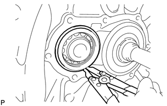
Using a snap ring expander, install a new snap ring to the counter gear front bearing.
33131A
5.INSTALL TRANSMISSION FRONT BEARING RETAINER OIL SEAL
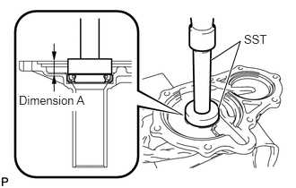
Using SST and a hammer, tap in a new oil seal to the retainer according to dimension A.
- SST
- 09950-70010 (09951-07100)
09950-60011 (09951-00480)
- Dimension A:
13.8 to 14.6 mm (0.543 to 0.575 in.)
Coat the lip of the oil seal with MP grease.
33124M
6.INSTALL NO. 4 OIL RECEIVER PIPE
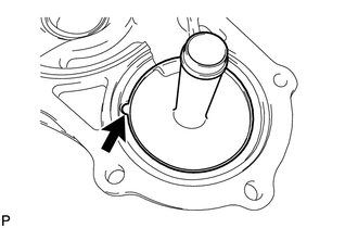
Install the oil receiver pipe to the transmission front bearing retainer.
- HINT:
-
When installing, align the turn stopper on the oil receiver with the groove on the bearing retainer.
33131
7.INSTALL FRONT BEARING RETAINER
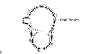
Apply FIPG (seal packing) to the retainer as shown in the illustration.
- FIPG:
Toyota Genuine Seal Packing 1281, Three Bond 1281 or equivalent.
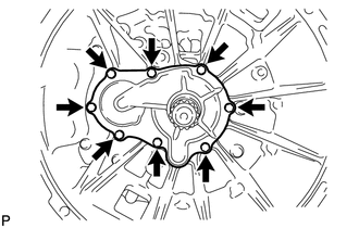
Coat the 8 bolts with sealant.
- Adhesive:
Toyota Genuine Adhesive 1344, Three Bond 1344 or equivalent.
- Torque:
17 N*m (173 kgf*cm, 13 ft.*lbf)
Install the transmission front bearing retainer with the 8 sealant-coated bolts.
Remove the rope from the input shaft and counter gear.
33321
8.INSTALL OUTPUT SHAFT
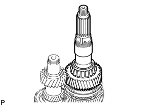
Coat the output shaft and synchronizer ring with gear oil, and install them.
33243A
9.INSTALL NO. 2 GEAR SHIFT FORK SHAFT
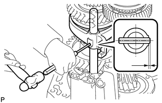
Coat the sliding and rotating surface of the gear shift fork and shift fork shaft with gear oil, and install them.
Using a pin punch (5 mm (0.20 in.)) and hammer, tap in the shaft fork slotted pin to the gear shift fork and shift fork shaft.
- Drive in depth:
0 to 1.0 mm (0 to 0.039 in.)
33242
10.INSTALL NO. 1 GEAR SHIFT FORK SHAFT
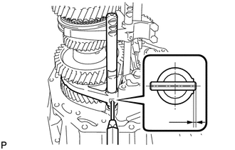
Coat the sliding and rotating gear shift fork and shift fork shaft with gear oil, and install them.
Using a pin punch (5 mm (0.20 in.)) and hammer, tap in the shift fork slotted pin to the gear shift fork and shift fork shaft.
- Drive in depth:
0 to 1.0 mm (0 to 0.039 in.)
33245G
11.INSTALL NO. 4 GEAR SHIFT FORK SHAFT
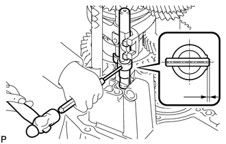
Coat the sliding and rotating surfaces of the gear shift fork and shift fork shaft with gear oil, and install them.
Using a pin punch (5 mm (0.20 in.)) and hammer, tap in the shift fork slotted pin to the gear shift fork guide and shift fork shaft.
- Drive in depth:
0 to 1.0 mm (0 to 0.039 in.)
33244D
12.INSTALL NO. 3 GEAR SHIFT FORK SHAFT
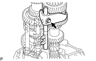
Coat the sliding and rotating surfaces of the gear shift fork and shift fork shaft with gear oil, and install them.
Install a new shift fork lock bolt to the gear shift fork and gear shift fork shaft.
- Torque:
46 N*m (469 kgf*cm, 34 ft.*lbf)
33275B
13.INSTALL SHAFT DETENT BALL
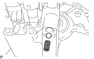
Install the ball and spring in the hole of the clutch housing.
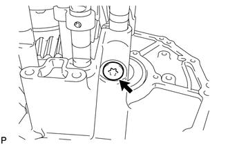
Using a "TORX" wrench (T40), install the plug to the clutch housing.
- Torque:
19 N*m (194 kgf*cm, 14 ft.*lbf)
33240
14.INSTALL REVERSE SHIFT ARM BRACKET ASSEMBLY
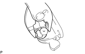
Install the reverse shift arm bracket assembly.
Using pliers, install a new E-ring to the shift lever.
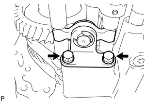
Install the shift lever to the clutch housing with the 2 bolts.
- Torque:
23 N*m (235 kgf*cm, 17 ft.*lbf)
33321A
15.INSTALL OUTPUT SHAFT REAR BEARING
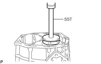
Using SST and a press, press in a new bearing to the transmission case.
- SST
- 09950-70010 (09951-07100)
09951-01000
33321V
16.INSTALL OUTPUT SHAFT CENTER BEARING (OUTER RACE)
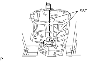
Using SST and a press, press in a new bearing to the transmission case.
- SST
- 09950-70010 (09951-07360)
09950-60021 (09951-00890)
33461
17.INSTALL REVERSE IDLER GEAR
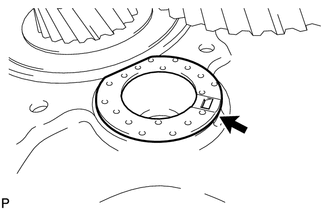
Aligning the turn stopper (protruding part) on the reverse idler gear thrust washer with the hole on the clutch housing.
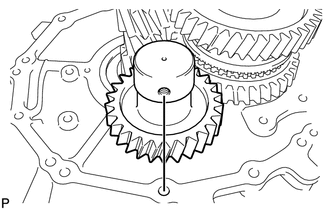
Coat the sliding and rotating surfaces of the reverse idler gear shaft, reverse idler gear needle roller bearing and reverse idler gear with gear oil, and install them.
- NOTICE:
-
Align the mark on the reverse idler gear shaft and bolt hole as shown in the illustration.
18.INSPECT REVERSE IDLER GEAR THRUST CLEARANCE
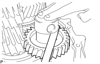
Using a feeler gauge, measure the thrust clearance of the reverse idler gear.
- Standard clearance:
0.10 to 0.62 mm (0.0039 to 0.0244 in.)
- Maximum clearance:
0.62 mm (0.0244 in.)
19.INSPECT REVERSE IDLER GEAR RADIAL CLEARANCE
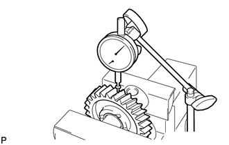
Using a dial indicator, measure the radial clearance of the reverse idler gear.
- Standard clearance:
0.015 to 0.059 mm (0.0006 to 0.0023 in.)
- Maximum clearance:
0.059 mm (0.0023 in.)
If the clearance exceeds the maximum, replace the reverse idler gear needle roller bearing.
33124D
20.INSTALL NO. 2 OIL RECEIVER PIPE
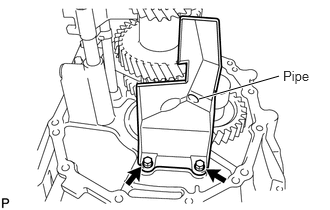
Install the oil receiver with the 2 bolts.
- Torque:
23 N*m (235 kgf*cm, 17 ft.*lbf)
- HINT:
-
Install the pipe of the oil receiver to the hole of the reverse idler gear shaft.
21.INSTALL TRANSMISSION OIL SEPARATOR
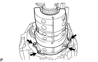
Install the oil separator with the 4 bolts.
- Torque:
23 N*m (235 kgf*cm, 17 ft.*lbf)
- HINT:
-
While installing the oil separator, slightly lift up the counter gear.
22.INSTALL NO. 2 SHIFT LEVER SHAFT OIL SEAL
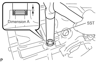
Using SST and a hammer, tap in a new select lever shaft oil seal to the transmission according to dimension A.
- SST
- 09950-70010 (09951-07100)
09950-60011 (09951-00200)
- Dimension A:
0 to 1.0 mm (0 to 0.039 in.)
Apply MP grease to the lip of the oil seal.
33126
23.INSTALL OIL RECEIVER SEAL
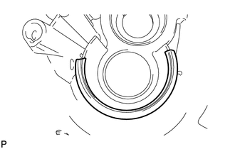
Install the seal to the transmission case.
33205
24.INSTALL SELECT LEVER SHAFT SUB-ASSEMBLY
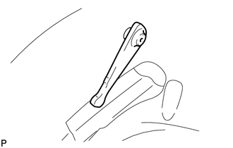
Install the shaft to the transmission case.
- NOTICE:
-
Make sure to set the select lever at the position shown in the illustration, otherwise you may have trouble at a later work.
33124C
25.INSTALL NO. 1 OIL RECEIVER PIPE
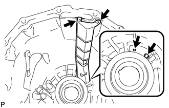
Install the oil receiver to the transmission case.
- HINT:
-
Insert the protruding part on the No. 1 oil receiver into the groove on the transmission case.
33101
26.INSTALL MANUAL TRANSMISSION CASE SUB-ASSEMBLY
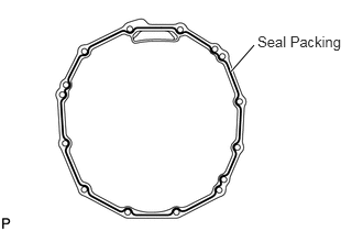
Apply FIPG (seal packing) to the transmission case as shown in the illustration.
- FIPG:
Toyota Genuine Seal Packing 1281, Three Bond 1281 or equivalent.
Install the transmission case to the clutch housing with the 12 bolts.
- Torque:
37 N*m (377 kgf*cm, 27 ft.*lbf)
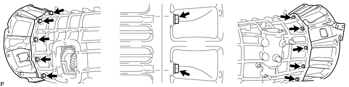
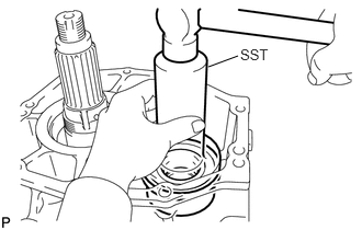
Using SST and a hammer, tap in a new counter gear rear bearing to the counter gear.
- SST
- 09309-36010
Install a new spacer and new output shaft rear tapered roller bearing to the output shaft.
Temporarily install a new output shaft adjusting nut to the output shaft.
Temporarily install a new counter gear rear nut to the counter gear.
27.INSTALL SHIFT DETENT BALL
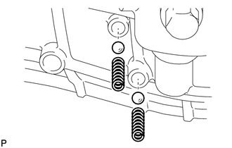
Install the 2 balls and 2 springs into the transmission case.
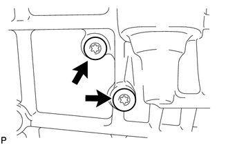
Using a "TORX" wrench (T40), install the 2 plugs to the transmission case.
- Torque:
19 N*m (194 kgf*cm, 14 ft.*lbf)
33451H
28.INSTALL REVERSE IDLER GEAR SHAFT BOLT
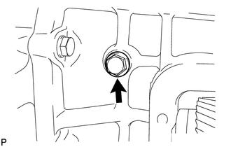
Install a new bolt to the transmission case.
- Torque:
28 N*m (286 kgf*cm, 21 ft.*lbf)
29.INSTALL SHIFT LEVER SHAFT HOUSING
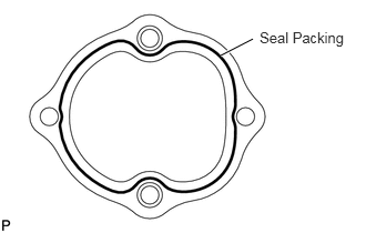
Apply FIPG (seal packing) to the housing as shown in the illustration.
- FIPG:
Toyota Genuine Seal Packing 1281, Three Bond 1281 or equivalent.
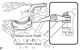
Install the select return spring to the transmission case.
Insert the tip of the select lever shaft into the hole on the select inner head.
- NOTICE:
-
Be careful not to let the select lever fall into the transmission case.
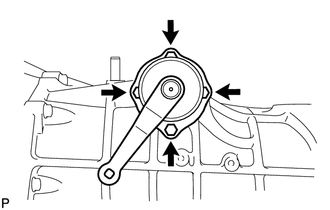
Install the housing to the transmission case with the 4 bolts.
- Torque:
17 N*m (173 kgf*cm, 13 ft.*lbf)
- NOTICE:
-
Be sure that the shift inner lever is inserted into the grooves on the No. 4 shift fork shaft and No. 2 shift fork.
33257
30.INSTALL SELECT OUTER LEVER
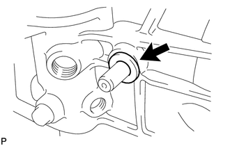
Install the washer to the select lever shaft.
Install the lever to the select lever shaft.
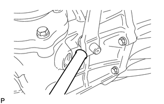
Using a brass bar hammer, tap in a new select lever shaft knock pin to the outer select lever.
Secure the knock pin with a new spring washer and the nut.
- Torque:
7.8 N*m (80 kgf*cm, 69 in.*lbf)
31.ADJUST OUTPUT SHAFT CENTER BEARING PRELOAD
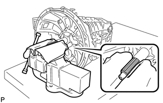
Fix the input shaft's spline part through 2 protective aluminum plates and a shop rag in a vise, and move the gear to the 4th place.
- NOTICE:
-
Be careful not to damage the spline area.
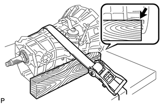
Using 2 belts and a wooden block, fasten the transmission to the work bench.
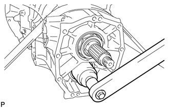
Using a 50 mm socket wrench, install the counter gear rear nut.
- Torque:
132 N*m (1,346 kgf*cm, 97 ft.*lbf)
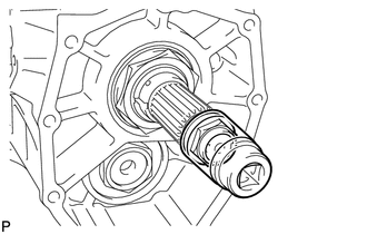
Install the output shaft rear set nut.
- HINT:
- ·
The output shaft rear set nut is used for measuring preload.
·The output shaft rear set nut code is 90179-24008.
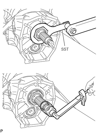
Using SST, tighten the output shaft adjusting nut so that the preload is within the standard.
- SST
- 09922-10010
- Preload (at starting):
0.3 to 0.8 N*m (3.06 to 8.16 kgf*cm 2.66 to 7.10 in.*lbf)
- HINT:
-
Before preload measurement, return the gear to neutral.
-
If the result is not as specified, tighten and adjust the output shaft adjusting nut.
- NOTICE:
-
If the output shaft adjusting nut is loosened or removed due to large preload, always replace the output shaft tapered roller bearing spacer with a new spacer.
Remove the output shaft rear set nut.
Remove the 2 belts and wooden block from the transmission assembly.
Return the gear to neutral and remove the input shaft from the vise.
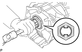
Using a chisel and hammer, caulk the output shift adjusting nut.
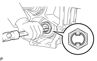
Using a chisel and hammer, caulk the counter gear lock nut.
32.INSTALL SPEEDOMETER DRIVE GEAR PIN
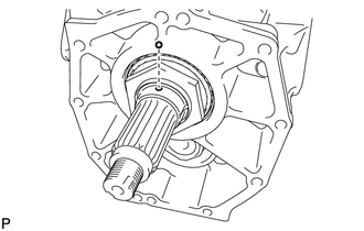
Apply MP grease to the pin (ball).
Install the pin (ball) in the output shaft.
33124L
33.INSTALL NO. 3 OIL RECEIVER PIPE
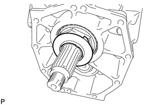
Install the No. 3 oil receiver pipe onto the output shaft.
34.INSTALL SPEEDOMETER DRIVE GEAR
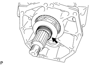
Install the speedometer drive gear onto the output shaft.
35469P
35.INSTALL TRANSMISSION REAR RETAINER SPACER
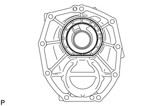
Install the transmission rear retainer spacer into the output shaft rear bearing retainer.
- NOTICE:
-
Be careful with the installation direction.
33141A
36.INSTALL TRANSMISSION REAR BEARING RETAINER OIL SEAL
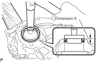
Place the transmission rear retainer on a wooden block.
Using SST and a hammer, tap in a new oil seal to the transmission case according to the dimension A.
- SST
- 09950-70010 (09951-07100)
09950-60011 (09951-00470, 09951-00610, 09952-06010)
- Dimension A:
0 to 0.5 mm (0 to 0.0120 in.)
Apply a light coat of grease to the lip of the transmission rear retainer oil seal.
37.INSTALL OUTPUT SHAFT REAR BEARING RETAINER
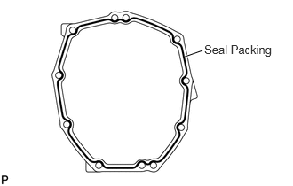
Apply FIPG (seal packing) to the retainer as shown in the illustration.
- FIPG:
Toyota Genuine Seal Packing 1281, Three Bond 1281 or equivalent.
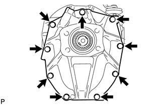
Install the retainer with the 9 bolts.
- Torque:
37 N*m (377 kgf*cm, 27 ft.*lbf)
38.INSTALL SPEEDOMETER DRIVEN GEAR SUB-ASSEMBLY
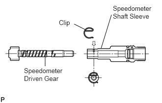
Install a new O-ring to the speedometer sleeve.
Install the driven gear to the speedometer sleeve with the clip.
- NOTICE:
-
Make sure to install the clip in the direction shown in the illustration.
Install the driven gear to the transmission rear bearing retainer.
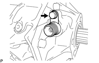
Install the speedometer sleeve lock plate to the transmission rear retainer with the bolt.
- Torque:
11 N*m (112 kgf*cm, 8 ft.*lbf)
33161
39.INSTALL MANUAL TRANSMISSION POWER TAKE-OFF COVER
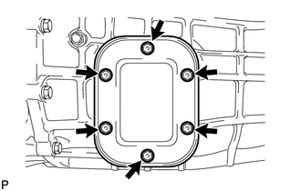
Install a new gasket and the power take-off cover with the 6 bolts.
- Torque:
14 N*m (143 kgf*cm, 10 ft.*lbf)
33101A
40.INSTALL MANUAL TRANSMISSION FILLER PLUG
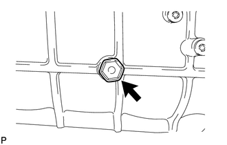
Install a new gasket and the filler plug to the transmission case.
- Torque:
37 N*m (377 kgf*cm, 27 ft.*lbf)
41.INSTALL DRAIN PLUG SUB-ASSEMBLY
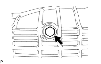
Install a new gasket and the drain plug to the transmission case.
- Torque:
37 N*m (377 kgf*cm, 27 ft.*lbf)
84540C
42.INSTALL EXHAUST BRAKE NEUTRAL SWITCH ASSEMBLY
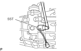
Using SST, install a new gasket and the neutral switch.
- SST
- 09817-16011
- Torque:
39 N*m (398 kgf*cm, 29 ft.*lbf)
43.INSTALL BACK-UP LIGHT SWITCH ASSEMBLY
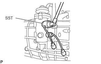
Using SST, install a new gasket and the back-up switch.
- SST
- 09817-16011
- Torque:
44 N*m (449 kgf*cm, 32 ft.*lbf)