M551 MANUAL TRANSMISSION / TRANSAXLE INPUT SHAFT INSPECTION
PROCEDURE

 33311
1.INSPECT INPUT SHAFT
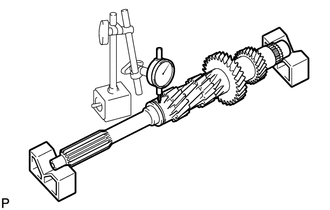
Using a dial indicator, measure the input shaft runout.
- Maximum runout:
0.015 mm (0.0006 in.)
If the runout exceeds the maximum, replace the input shaft assembly.
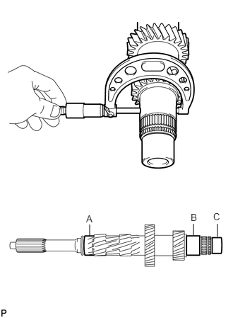
Using a micrometer, measure the outer diameters of the input shaft journal surface.
| Part | Outer diameter |
|---|---|
| A | 47.002 to 47.018 mm (1.8505 to 1.8511 in.) |
| B | 47.984 to 48.000 mm (1.8891 to 1.8898 in.) |
| C | 38.118 to 38.130 mm (1.5007 to 1.5012 in.) |
| Part | Outer diameter |
|---|---|
| A | 47.002 mm (1.8505 in.) |
| B | 47.984 mm (1.8891 in.) |
| C | 38.118 mm (1.5007 in.) |
If one of the diameters is less than the minimum, replace the input shaft.
33336
2.INSPECT 5TH GEAR
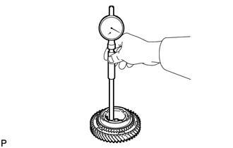
Using a cylinder gauge, measure the inside diameter of the gear.
- Standard inside diameter:
55.015 to 55.040 mm (2.1659 to 2.1669 in.)
- Maximum inside diameter:
55.040 mm (2.1669 in.)
If the diameter exceeds the maximum, replace the 5th gear.
33346B
3.INSPECT 5TH GEAR THRUST WASHER
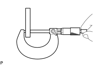
Using a micrometer, measure the thrust washer thickness.
- Standard thickness:
4.95 to 5.05 mm (0.1945 to 0.2004 in.)
- Minimum thickness:
4.95 mm (0.1945 in.)
If the thickness is less than the minimum, replace the 5th gear thrust washer.
33368J
4.INSPECT 5TH GEAR SYNCHRONIZER RING
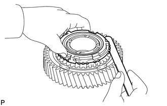
Using a feeler gauge, measure the clearance between the synchronizer ring and gear spline.
- Standard clearance:
0.78 to 1.62 mm (0.0307 to 0.0638 in.)
- Minimum clearance:
0.78 mm (0.0307 in.)
If the clearance is less than the minimum, replace the synchronizer ring.
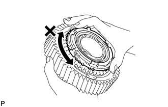
Coat the 5th gear cone with gear oil. Check the braking effect of the synchronizer ring. Turn the synchronizer ring in one direction while pushing it to the gear cone. Check that the ring locks.
33395
5.INSPECT NO. 3 TRANSMISSION HUB SLEEVE
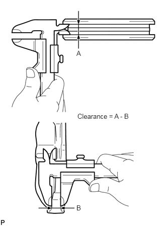
Using a vernier caliper, measure the wide of the hub sleeve and thickness of the No. 3 gear shift fork as shown in the illustration.
Calculate the clearance using the formula below.
- Formula:
Clearance = A - B
- Standard:
0.15 to 0.35 mm (0.0059 to 0.0138 in.)
If the clearance is not as specified, replace the No. 3 transmission hub sleeve and No. 3 gear shift fork.
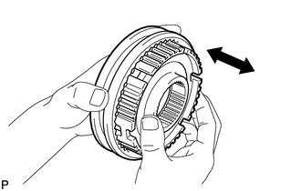
Check the sliding condition between the hub sleeve and clutch hub.
Check that the spline gear's edges of the hub sleeve are not worn down.