M551 MANUAL TRANSMISSION / TRANSAXLE INPUT SHAFT REASSEMBLY
PROCEDURE

 33311A
1.INSTALL INPUT SHAFT FRONT BEARING
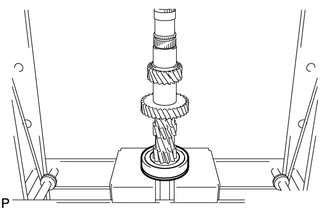
Using a press, press on a new bearing.
33311B
2.INSTALL FRONT BEARING SHAFT SNAP RING
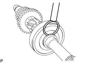
Select a snap ring that allows minimum axial play.
- Standard clearance:
0.10 mm (0.0039 in.) or less
Mark Specified Condition A 3.00 to 3.05 mm (0.1181 to 0.1201 in.) B 3.05 to 3.10 mm (0.1201 to 0.1220 in.) C 3.10 to 3.15 mm (0.1220 to 0.1240 in.) D 3.15 to 3.20 mm (0.1240 to 0.1260 in.) E 3.20 to 3.25 mm (0.1260 to 0.1280 in.) F 3.25 to 3.30 mm (0.1280 to 0.1300 in.)
Using a brass bar and hammer, tap in a new snap ring.
33342A
3.INSTALL GEAR THRUST WASHER STRAIGHT PIN
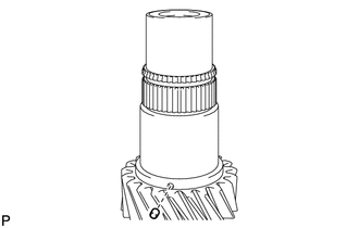
Coat the pin (ball) with MP grease and install it.
33346B
4.INSTALL 5TH GEAR THRUST WASHER
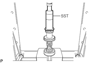
Using SST and a press, press on the thrust washer.
- SST
- 09316-60012 (09316-00011)
33368J
5.INSTALL 5TH GEAR SYNCHRONIZER RING
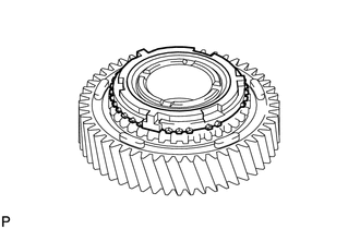
Coat the synchronizer ring with gear oil and install it to the 5th gear.
33336A
6.INSTALL 5TH GEAR NEEDLE ROLLER BEARING
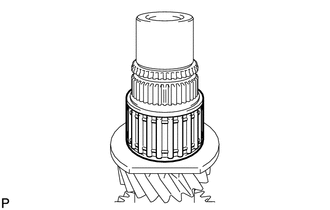
Coat the bearing with gear oil and install it.
33393
7.INSTALL NO. 3 TRANSMISSION CLUTCH HUB
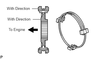
Coat the hub sleeve with gear oil and install it to the clutch hub.
- HINT:
-
Set the hub sleeve and the clutch hub in correct orientation.
Install the 2 key springs and 3 keys to the hub sleeve.
- NOTICE:
-
Do not set both opening of the shifting key springs in the same position.
33336
8.INSTALL 5TH GEAR
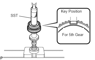
Coat the gear with gear oil.
Using SST and a press, press in the gear.
- SST
- 09316-60012 (09316-00011)
33393A
9.INSTALL TRANSMISSION CLUTCH HUB NO. 3 SHAFT SNAP RING
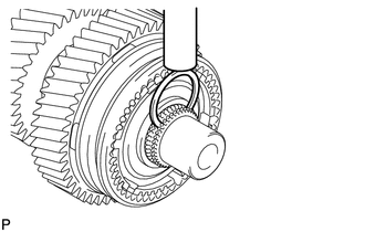
Select a snap ring that will allow minimum axial play.
- Standard clearance:
0.10 mm (0.0039 in.) or less
Mark Specified Condition A 2.60 to 2.65 mm (0.1024 to 0.1043 in.) B 2.65 to 2.70 mm (0.1043 to 0.1063 in.) C 2.70 to 2.75 mm (0.1063 to 0.1083 in.) D 2.75 to 2.80 mm (0.1083 to 0.1102 in.) E 2.80 to 2.85 mm (0.1102 to 0.1122 in.) F 2.85 to 2.90 mm (0.1122 to 0.1142 in.)
Using a brass bar and hammer, and tap in the snap ring.
10.INSPECT 5TH GEAR THRUST CLEARANCE
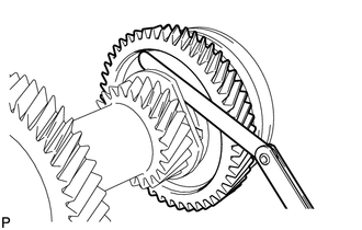
Using a feeler gauge, measure the gear thrust clearance.
- Standard clearance:
0.10 to 0.35 mm (0.039 to 0.0138 in.)
- Maximum clearance:
0.35 mm (0.0138 in.)
11.INSPECT 5TH GEAR RADIAL CLEARANCE
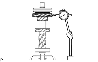
Using a dial indicator, measure the radial clearance between the gear and shaft.
- Standard clearance:
0.015 to 0.068 mm (0.0006 to 0.0027 in.)
- Maximum clearance:
0.068 mm (0.0027 in.)
If the clearance is not as specified, replace the 5th gear needle roller bearing.