M551 MANUAL TRANSMISSION / TRANSAXLE COUNTER GEAR AND REVERSE IDLER GEAR DISASSEMBLY
PROCEDURE

 1.INSPECT REVERSE GEAR THRUST CLEARANCE
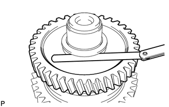
Fix the counter gear through 2 protective aluminum plates in a vise.
Using a feeler gauge, measure the counter gear thrust clearance.
- Standard clearance:
0.10 to 0.45 mm (0.0039 to 0.0177 in.)
- Maximum clearance:
0.45 mm (0.0177 in.)
2.INSPECT REVERSE GEAR RADIAL CLEARANCE
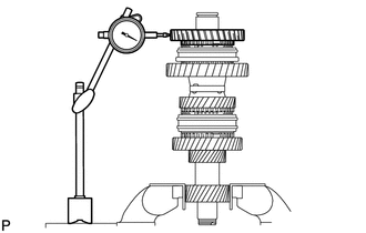
Using a dial indicator, measure the reverse gear radial clearance between the gear and shaft.
- Standard clearance:
0.015 to 0.068 mm (0.0006 to 0.0027 in.)
- Maximum clearance:
0.068 mm (0.0027 in.)
If the clearance exceeds the maximum, replace the reverse gear needle roller bearing.
3.INSPECT 1ST GEAR THRUST CLEARANCE
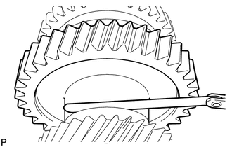
Using a feeler a gauge, measure the gear thrust clearance.
- Standard clearance:
0.10 to 0.45 mm (0.0039 to 0.0177 in.)
- Maximum clearance:
0.45 mm (0.0177 in.)
4.INSPECT 1ST GEAR RADIAL CLEARANCE
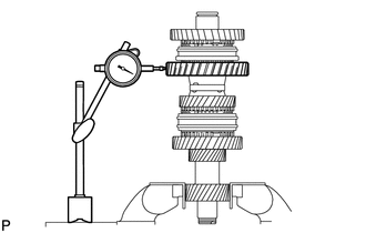
Using a dial indicator, measure the 1st gear radial clearance between the gear and shaft.
- Standard clearance:
0.015 to 0.068 mm (0.0006 to 0.0027 in.)
- Maximum clearance:
0.068 mm (0.0027 in.)
If the clearance exceeds the maximum, replace the gear needle roller bearing.
5.INSPECT 3RD GEAR THRUST CLEARANCE
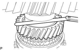
Using a feeler gauge, measure the gear thrust clearance.
- Standard clearance:
0.10 to 0.45 mm (0.0039 to 0.0177 in.)
- Maximum clearance:
0.45 mm (0.0177 in.)
6.INSPECT 3RD GEAR RADIAL CLEARANCE
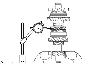
Using a dial indicator, measure the gear radial clearance between the gear and shaft.
- Standard clearance:
0.015 to 0.068 mm (0.0006 to 0.0027 in.)
- Maximum clearance:
0.068 mm (0.0027 in.)
If the clearance exceeds the maximum, replace the 3rd gear needle roller bearing.
7.INSPECT 2ND GEAR THRUST CLEARANCE
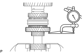
Using a dial indicator, measure the gear thrust clearance.
- Standard clearance:
0.10 to 0.35 mm (0.0039 to 0.0138 in.)
- Maximum clearance:
0.35 mm (0.0138 in.)
8.INSPECT 2ND GEAR RADIAL CLEARANCE
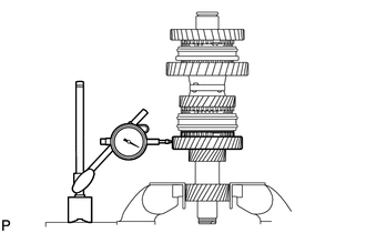
Using a dial indicator, measure the gear radial clearance between the gear and shaft.
- Standard clearance:
0.015 to 0.068 mm (0.0006 to 0.0027 in.)
- Maximum clearance:
0.068 mm (0.0027 in.)
If the clearance exceeds the maximum, replace the 2nd gear needle roller bearing.
9.REMOVE COUNTER GEAR FRONT NO. 2 BEARING SNAP RING
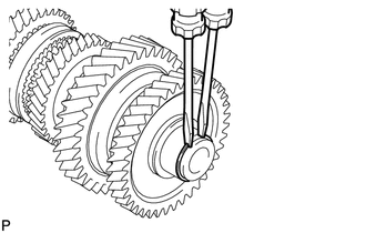
Using 2 screwdrivers and a hammer, tap out the snap ring.
- NOTICE:
-
Use a shop rag or piece of cloth to prevent the snap ring from flying off.
10.REMOVE REVERSE GEAR
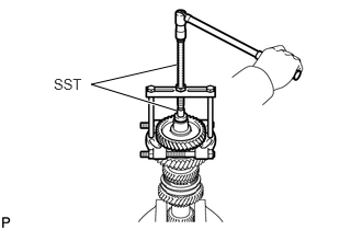
Using SST, remove the reverse gear and counter gear front bearing (inner race).
- SST
- 09950-00020
09950-00030
09950-40011 (09957-04010)
09950-60011 (09951-00180, 09951-00370, 09952-06010)
33387A
11.REMOVE REVERSE SYNCHRONIZER RING
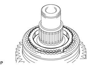
Remove the reverse synchronizer ring from the counter gear.
33331A
12.REMOVE REVERSE GEAR BEARING
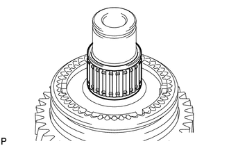
Remove the reverse gear bearing from the counter gear.
33361B
13.REMOVE CLUTCH HUB NO. 1 SHAFT SNAP RING
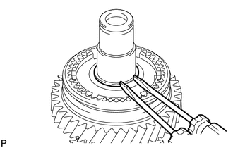
Using 2 screwdrivers and a hammer, tap out the snap ring.
- NOTICE:
-
Use a shop rag or piece of cloth to prevent the snap ring from flying off.
14.REMOVE 1ST GEAR
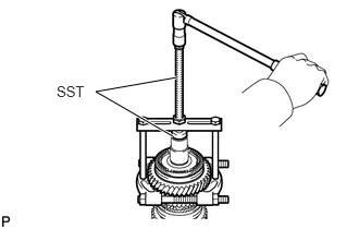
Using SST, remove the 1st gear, transmission clutch hub No. 1 and synchronizer ring.
- SST
- 09950-00020
09950-00030
09950-40011 (09957-04010)
09950-60011 (09951-00370)
33361
15.REMOVE NO. 1 TRANSMISSION CLUTCH HUB
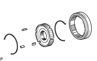
Using a screwdriver, remove the 2 key springs, 3 keys and hub sleeve from the clutch hub.
33335C
16.REMOVE 1ST GEAR NEEDLE ROLLER BEARING
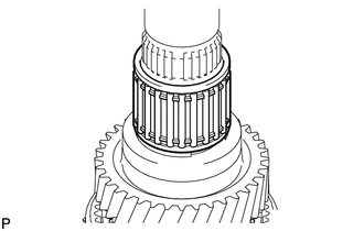
Remove the 1st gear needle roller bearing from the counter gear.
33342B
17.REMOVE GEAR THRUST WASHER SHAFT SNAP RING
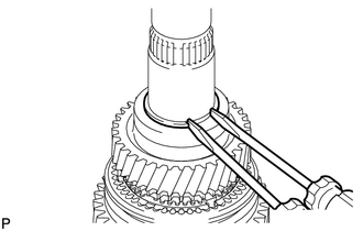
Using 2 screwdrivers and a hammer, tap out the snap ring from the counter gear.
- NOTICE:
-
Use a shop rag or piece of cloth to prevent the snap ring from flying off.
33333
18.REMOVE 3RD GEAR
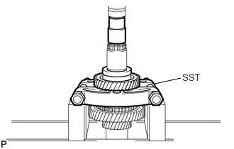
Using SST and a press, press out the thrust washer.
- SST
- 09950-00020
33342A
19.REMOVE GEAR THRUST WASHER STRAIGHT PIN
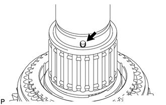
Remove the pin.
33333A
20.REMOVE 3RD GEAR NEEDLE ROLLER BEARING
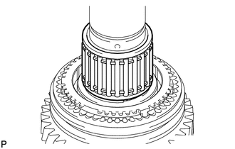
Remove the 3rd gear needle roller bearing from the counter gear.
33368G
21.REMOVE 3RD GEAR SYNCHRONIZER RING
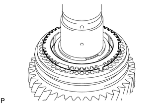
Remove the 3rd gear synchronizer ring from the counter gear.
33362A
22.REMOVE CLUTCH HUB NO. 2 SETTING SHAFT SNAP RING
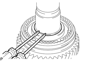
Using 2 screwdrivers and a hammer, tap out snap ring.
- NOTICE:
-
Use a shop rag or piece of cloth to prevent the snap ring from flying off.
23.REMOVE 2ND GEAR
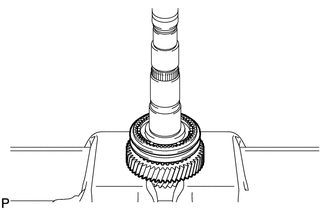
Using a press, press out the 2nd gear, transmission clutch hub No. 2 and synchronizer ring.
33362
24.REMOVE NO. 2 TRANSMISSION CLUTCH HUB
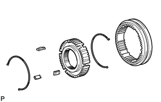
Using a screwdriver, remove the 2 key springs, 3 keys and hub sleeve from the clutch hub.
33332B
25.REMOVE 2ND GEAR NEEDLE ROLLER BEARING
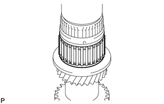
Remove the 2nd gear needle roller bearing from the counter gear.
33341A
26.REMOVE 2ND GEAR THRUST WASHER
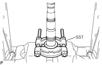
Using SST and a press, press out the thrust washer.
- SST
- 09950-00020
33342A
27.REMOVE GEAR THRUST WASHER STRAIGHT PIN
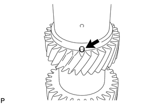
Remove the pin from the counter gear.