M551 MANUAL TRANSMISSION / TRANSAXLE COUNTER GEAR AND REVERSE IDLER GEAR INSPECTION
PROCEDURE

 33421
1.INSPECT COUNTER GEAR
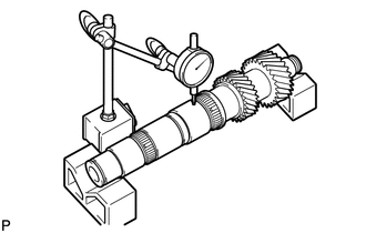
Using a dial indicator, measure the shaft runout.
- Maximum runout:
0.015 mm (0.0006 in.)
If the runout exceeds the maximum, replace the counter shaft assembly.
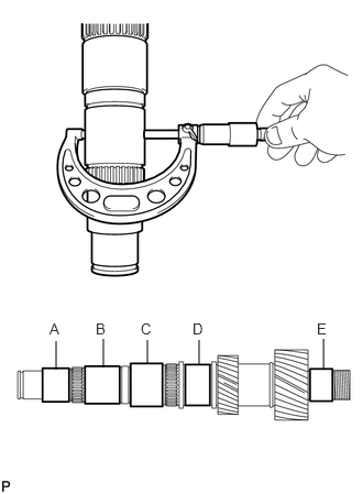
Using a micrometer, measure the diameter of the counter shaft journal surface.
| Part | Outer diameter |
|---|---|
| A | 43.484 to 43.500 mm (1.7120 to 1.7126 in.) |
| B | 48.984 to 49.000 mm (1.9285 to 1.9291 in.) |
| C | 53.984 to 54.000 mm (2.1253 to 2.1260 in.) |
| D | 53.984 to 54.000 mm (2.1253 to 2.1260 in.) |
| E | 40.002 to 40.018 mm (1.5749 to 1.5755 in.) |
| Part | Outer diameter |
|---|---|
| A | 43.484 mm (1.7120 in.) |
| B | 48.984 mm (1.9285 in.) |
| C | 53.984 mm (2.1253 in.) |
| D | 53.984 mm (2.1253 in.) |
| E | 40.002 mm (1.5749 in.) |
If the diameter is less than the minimum, replace the output shaft.
2.INSPECT REVERSE GEAR
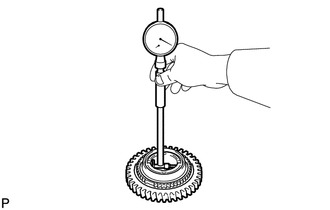
Using a cylinder gauge, measure the inside diameter of the gear.
- Standard inside diameter:
50.515 to 50.540 mm (1.9888 to 1.9898 in.)
- Maximum inside diameter:
50.540 mm (1.9898 in.)
If the inside diameter exceeds the maximum, replace the reverse gear.
3.INSPECT 1ST GEAR
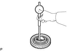
Using a cylinder gauge, measure the inside diameter of the gear.
- Standard inside diameter:
56.015 to 56.040 mm (2.2053 to 2.2063 in.)
- Maximum inside diameter:
56.040 mm (2.2063 in.)
If the inside diameter exceeds the maximum, replace the 1st gear.
4.INSPECT 2ND GEAR
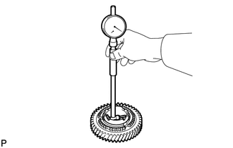
Using a cylinder gauge, measure the inside diameter of the gear.
- Standard inside diameter:
61.015 to 61.040 mm (2.4022 to 2.4031 in.)
- Maximum inside diameter:
61.040 mm (2.4031 in.)
If the inside diameter exceeds the maximum, replace the 2nd gear.
33333
5.INSPECT 3RD GEAR
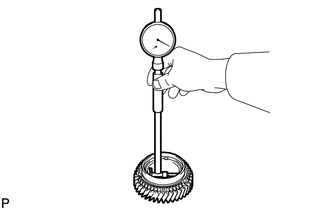
Using a cylinder gauge, measure the inside diameter of the 3rd gear.
- Standard inside diameter:
61.015 to 61.040 mm (2.4022 to 2.4031 in.)
- Maximum inside diameter:
61.040 mm (2.4031 in.)
If the inside diameter exceeds the maximum, replace the 3rd gear.
33342C
6.INSPECT 3RD GEAR THRUST WASHER
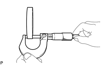
Using a micrometer, measure the thrust washer thickness.
- Standard thickness:
11.45 to 11.55 mm (0.4508 to 0.4547 in.)
- Minimum thickness:
11.45 mm (0.4508 in.)
If the thickness is less than the minimum, replace the 3rd gear thrust washer.
33341A
7.INSPECT 2ND GEAR THRUST WASHER
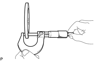
Using a micrometer, measure the thrust washer thickness.
- Standard thickness:
5.45 to 5.55 mm (0.2146 to 0.2185 in.)
- Minimum thickness:
5.45 mm (0.2146 in.)
If the thickness is less than the minimum, replace the 2nd gear thrust washer.
33037B
8.INSPECT NO. 1 SYNCHRONIZER RING SET
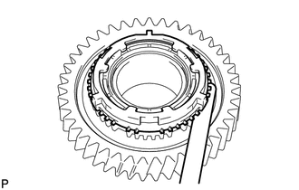
Using a feeler gauge, measure the clearance between the synchronizer ring and 1st gear spline.
- Standard clearance:
1.10 to 2.10 mm (0.0433 to 0.0827 in.)
- Minimum clearance:
1.10 mm (0.0433 in.)
If the clearance is less than the minimum, replace the synchronizer ring.
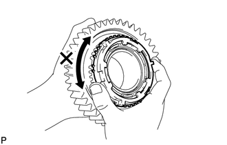
Coat the 1st gear cone with gear oil. Check the braking effect of the synchronizer ring. Turn the synchronizer ring in one direction while pushing it to the 1st gear cone. Check that the ring locks.
If the braking effect is insufficient, apply a small amount of the fine lapping compound between the synchronizer ring and 1st gear cone. Lightly rub the synchronizer ring and 1st gear cone together.
- NOTICE:
-
Ensure the fine lapping compound is completely washed off after rubbing.
Check again the braking effect of the synchronizer ring.
33387A
9.INSPECT REVERSE SYNCHRONIZER RING
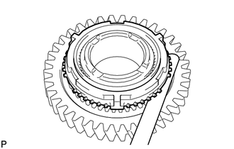
Using a feeler gauge, measure the clearance between the synchronizer ring and reverse gear spline.
- Standard clearance:
0.78 to 1.62 mm (0.0307 to 0.0638 in.)
- Minimum clearance:
0.78 mm (0.0307 in.)
If the clearance is less than the minimum, replace the reverse synchronizer ring.
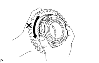
Coat the reverse gear cone with gear oil. Check the braking effect of the synchronizer ring. Turn the synchronizer ring in one direction while pushing it to the reverse gear cone. Check that the ring locks.
If the braking effect is insufficient, apply a small amount of the fine lapping compound between the synchronizer ring and reverse gear cone. Lightly rub the synchronizer ring and reverse gear cone together.
- NOTICE:
-
Ensure the fine lapping compound is completely washed off after rubbing.
Check again the braking effect of the synchronizer ring.
33368G
10.INSPECT 3RD GEAR SYNCHRONIZER RING
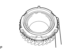
Using a feeler gauge, measure the clearance between the synchronizer ring and 3rd gear spline end.
- Standard clearance:
0.78 to 1.62 mm (0.0307 to 0.0643 in.)
- Minimum clearance:
0.78 mm (0.0307 in.)
If the clearance is less than the minimum, replace the synchronizer ring.
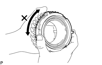
Coat the 3rd gear cone with gear oil. Check the braking effect of the synchronizer ring. Turn the synchronizer ring in one direction while pushing it to the 3rd gear cone. Check that the ring locks.
If the braking effect is insufficient, apply a small amount of the fine lapping compound between the synchronizer ring and 3rd gear cone. Lightly rub the synchronizer ring and 3rd gear cone together.
- NOTICE:
-
Ensure the fine lapping compound is completely washed off after rubbing.
Check again the braking effect of the synchronizer ring.
33038E
11.INSPECT NO. 2 SYNCHRONIZER RING SET
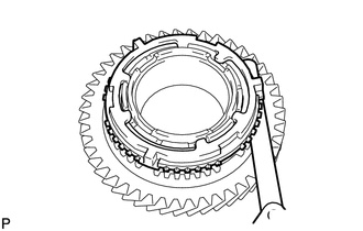
Using a feeler gauge, measure the clearance between the synchronizer ring and 2nd gear spline.
- Standard clearance:
1.10 to 2.10 mm (0.0433 to 0.0827 in.)
- Minimum clearance:
1.10 mm (0.0433 in.)
If the clearance is less than the minimum, replace the synchronizer ring.
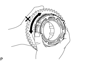
Coat the 2nd gear cone with gear oil. Check the braking effect of the synchronizer ring. Turn the synchronizer ring in one direction while pushing it to the 2nd gear cone. Check that the ring locks.
If the braking effect is insufficient, apply a small amount of the fine lapping compound between the synchronizer ring and 2nd gear cone. Lightly rub the synchronizer ring and 2nd gear cone together.
- NOTICE:
-
Ensure the fine lapping compound is completely washed off after rubbing.
Check again the braking effect of the synchronizer ring.
33363
12.INSPECT NO. 1 TRANSMISSION HUB SLEEVE
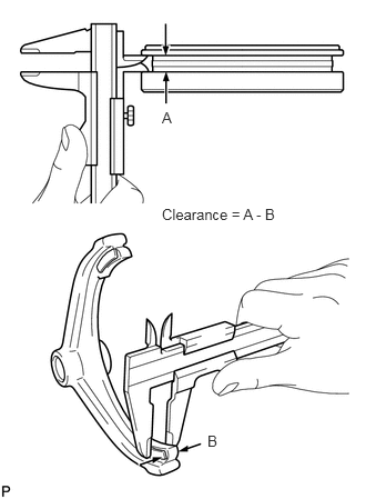
Using a vernier caliper, measure the wide of the hub sleeve and thickness of the No. 1 gear shift fork as shown in the illustration.
Calculate the clearance using the formula below.
- Formula:
Clearance = A - B
- Standard:
0.25 to 0.85 mm (0.0098 to 0.0335 in.)
If the result is not as specified, replace the No. 1 transmission hub sleeve and No. 1 gear shift fork.
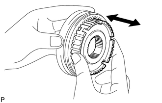
Check the sliding condition between the hub sleeve and clutch hub.
33364
13.INSPECT NO. 2 TRANSMISSION HUB SLEEVE
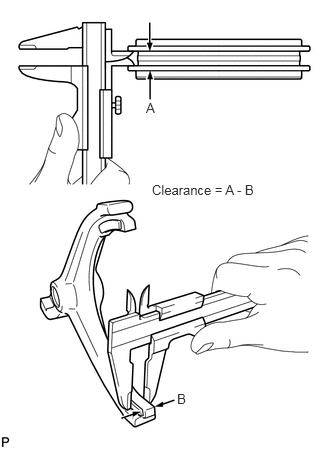
Using a vernier caliper, measure the clearance between No. 2 gear shift fork and No. 2 transmission hub sleeve.
Calculate the clearance using the formula below.
- Formula:
Clearance = A - B
- Standard clearance:
0.25 to 0.85 mm (0.0098 to 0.0335 in.)
If the clearance exceeds the standard, replace the No. 2 gear shift fork and No. 2 transmission hub sleeve.
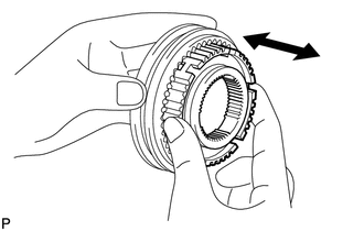
Check the sliding condition between the hub sleeve and clutch hub.