M551 MANUAL TRANSMISSION / TRANSAXLE SHIFT LEVER SHAFT HOUSING REASSEMBLY
PROCEDURE

 33203B
1.INSTALL SHIFT LEVER SHAFT OIL SEAL
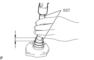
Using SST and a hammer, tap in a new oil seal to the control shaft cover.
- SST
- 09950-70010 (09951-07100)
09950-60011 (09951-00310)
- Drive in depth:
0 to 1.0 mm (0 to 0.0394 in.)
Coat the control shaft cover oil seal with MP grease.
33506D
2.INSTALL CONTROL SHAFT COVER SUB-ASSEMBLY
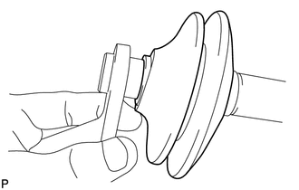
Coat the shift lever shaft and boot with MP grease.
Install the control shaft cover to the shift lever shaft.
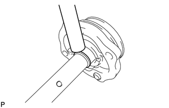
Using a brass bar and hammer, tap in a new snap ring to the shift lever shaft.
33237B
3.INSTALL SELECT HEAD INNER
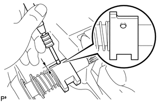
Fix the select lever shaft lever shaft through 2 protective aluminum plates in a vise.
Coat the select spring seat with MP grease.
Install the select spring seat, select return spring and select head inner to the shift lever shaft.
Using a pin punch (5 mm (0.20 in.)) and hammer, tap in a new slotted pin to the shift lever shaft.
- Drive in depth:
0 to 1.0 mm (0 to 0.0394 in.)
- NOTICE:
-
Be careful with the installation direction of the select inner head.
33251A
4.INSTALL NO. 1 SHIFT LEVER INNER
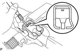
Coat the shift lever and shift inner lock plate with MP grease.
Install the shift lever and shift inner lock plate to the shift lever shaft.
Using a pin punch (5 mm (0.20 in.)) and hammer, tap in a new slotted pin to the shift lever shaft.
- Drive in depth:
0 to 1.0 mm (0 to 0.0394 in.)
- NOTICE:
-
Be careful with the installation directions of the shift lever inner No. 1 and shift interlock plate.
Remove the shift lever shaft from the vise.