RM2850E
_58
Vehicle Interior
_073188
DOOR LOCK
_0356159
DOOR CONTROL RELAY(for Emergency Door)
G
DOOR LOCK DOOR CONTROL RELAY(for Emergency Door) ON-VEHICLE INSPECTION
PROCEDURE

 85980K
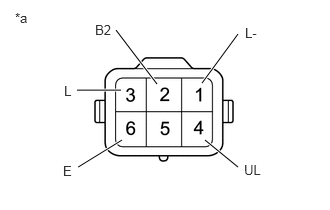
1.INSPECT NO. 2 DOOR LOCK RELAY ASSEMBLY
a.
1.208,0.313 1.635,0.875
true
0.813,1.74 1.271,1.458
true
0.802,0.938 1.26,0.938
true
2.479,1.74 2.135,1.458
true
2.104,0.865 2.479,0.354
true
0.99,0.229 1.302,0.427
0.313,0.198
10
false
B2
2.552,0.26 2.865,0.458
0.313,0.198
10
false
L-
0.667,0.865 0.979,1.063
0.313,0.198
10
false
L
0.656,1.698 0.969,1.896
0.313,0.198
10
false
E
2.542,1.688 2.854,1.885
0.313,0.198
10
false
UL
0.156,0.104 0.469,0.302
0.313,0.198
10
false
*a
Measure the resistance according to the value(s) in the table below.
- Standard Resistance:
Tester Connection Condition Specified Condition 3 (L) - 1 (L-) Battery voltage not applied between terminals 2(B2) and 6(E) Below 1 Ω Battery voltage applied between terminals 2(B2) and 6(E) 10 kΩ or higher 4 (UL) - 1 (L-) Battery voltage not applied between terminals 2(B2) and 6(E) 10 kΩ or higher Battery voltage applied between terminals 2(B2) and 6(E) Below 1 Ω
| *a | Component with harness connected
(No. 2 Door Lock Relay Assembly) |
If the result is not as specified, replace the No. 2 door lock relay assembly.
85980J
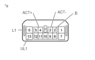
2.INSPECT AND ADJUST NO. 1 DOOR LOCK RELAY ASSEMBLY
a.
1.417,1.01 1.198,0.479
true
1.833,1.021 2.01,0.438
true
2.01,1.031 2.646,0.49
true
0.656,1.094 0.979,1.094
true
0.854,1.677 1.031,1.385
true
0.167,0.125 0.479,0.323
0.313,0.198
10
false
*a
0.813,0.375 1.354,0.604
0.542,0.229
10
false
ACT+
2.083,0.354 2.625,0.583
0.542,0.229
10
false
ACT-
0.438,1.021 0.708,1.26
0.271,0.24
10
false
L1
0.74,1.688 1.354,2.031
0.615,0.344
10
false
UL1
2.708,0.396 3.25,0.625
0.542,0.229
10
false
B
Measure the voltage according to the value(s) in the table below.
- Standard Resistance:
Tester Connection Condition Specified Condition 2 (B) - Body Grand Always 9.5 to 15 V 6 (L1) - Body Grand Ignition switch off → Ignition switch on Below 1 V → 9.5 to 15 V 13 (UL1) - Body Grand Ignition switch on → Ignition switch off 9.5 to 15 V → approximate 4 V 3 (ACT-) - Body Grand Ignition switch on → Ignition switch off 3.5 V → 9.5 to 15 V → 3.5 V 4 (ACT+) - Body Grand Ignition switch off → Ignition switch on Below 1 V → 9.5 to 15 V → 3.5 V
| *a | Component with harness connected
(No. 1 Door Lock Relay Assembly) |
If the result is not as specified, replace the No. 1 door lock relay assembly.