POWER ASSIST SYSTEMS VANE PUMP(for N04C Series Engine) REASSEMBLY
PROCEDURE

 44302G
1.INSTALL VANE PUMP HOUSING OIL SEAL
Apply a small amount of MP grease to the lip of a new vane pump housing oil seal.
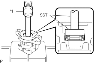
Using SST and a press, install vane pump housing oil seal, in the direction shown in the illustration, into the vane pump front housing.
- SST
- 09950-70010 (09951-07150)
09950-60011 (09951-00320)
| *1 | Press |
- NOTICE:
- ·
Install the vane pump housing oil seal in the correct direction.
·Do not damage the vane pump housing oil seal.
44312A
2.INSTALL VANE PUMP SHAFT BEARING
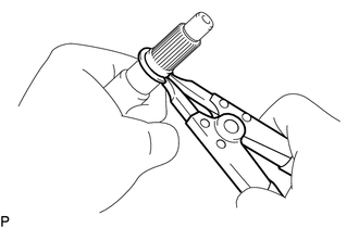
Using a snap ring expander, install a new snap ring onto the vane pump shaft.
Apply protective tape to the serrated part of the vane pump shaft.
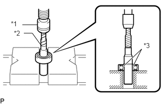
Using a press, install a new vane pump shaft bearing into the vane pump shaft.
| *1 | Press |
| *2 | Protective Tape |
| *3 | Inner Race |
- NOTICE:
- ·
Do not damage the vane pump shaft bearing.
·Place the vane pump shaft bearing inner race on the base of the press, as shown in the illustration.
44316
3.INSTALL VANE PUMP GEAR
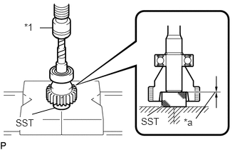
Using SST and a press, install the vane pump shaft with bearing into the vane pump gear.
| *1 | Press |
| *a | Press in |
- SST
- 09950-60011 (09951-00250)
- HINT:
-
Install the vane pump shaft into the vane pump gear until it is flush with the end.
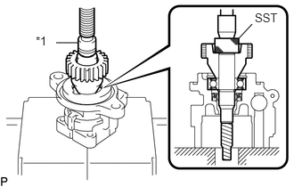
Using SST and a press, install the vane pump gear into the vane pump front housing.
| *1 | Press |
- SST
- 09950-60011 (09951-00250)
- HINT:
-
Insert the vane pump gear until the ring groove of the vane pump front housing can be seen.
Install a new snap ring onto the vane pump front housing.
Remove the protective tape from the vane pump shaft.
4.INSTALL VANE PUMP FRONT SIDE PLATE
Coat a new O-ring with power steering fluid.
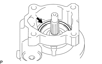
Install the O-ring into the vane pump front housing.
Coat a new O-ring with power steering fluid.
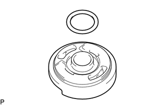
Install the O-ring onto the vane pump front side plate.
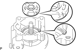
Align the dent of the vane pump front side plate with that of the vane pump front housing and install the side plate into the vane pump front housing.
- NOTICE:
-
Install the vane pump front side plate in the correct direction and location.
5.INSTALL VANE PUMP CAM RING
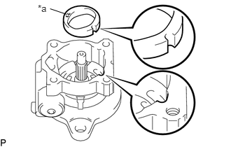
Align the indentation on the vane pump cam ring with that of the vane pump front housing and install the vane pump cam ring into the vane pump front housing with the inscribed mark facing outward.
| *a | Inscribed Mark |
- NOTICE:
-
Install the vane pump cam ring in the correct direction and location.
6.INSTALL VANE PUMP ROTOR
Install the vane pump rotor onto the vane pump shaft.
- HINT:
-
The vane pump rotor can be installed in either direction.
Coat the 10 vane pump plates with power steering fluid.
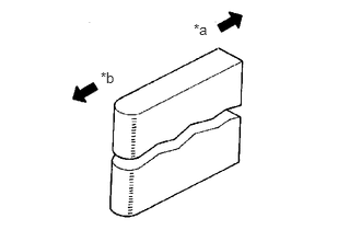
Install the 10 vane pump plates with the round ends facing outward.
| *a | Inside |
| *b | Outside |
- NOTICE:
-
Install the vane pump plates in the correct direction.
44304
7.INSTALL VANE PUMP REAR HOUSING
Coat a new O-ring with power steering fluid.
Install the O-ring onto the vane pump rear housing.
- NOTICE:
-
Make sure that the O-ring is securely installed in the O-ring groove of the vane pump rear housing.
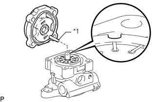
Align the straight pin of the vane pump rear housing with the indentation on the vane pump cam ring and provisionally install the vane pump rear housing onto the vane pump front housing.
| *1 | Straight Pin |
- NOTICE:
-
Make sure that the O-ring is securely installed in the groove before installing the vane pump rear housing.
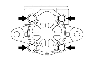
Install the vane pump rear housing onto the vane pump front housing with the 4 bolts.
- Torque:
22 N*m (224 kgf*cm, 16 ft.*lbf)
8.INSPECT PRELOAD
Check that the vane pump gear rotates smoothly without making any abnormal noises.
Install the bolt onto the vane pump shaft.
- Recommended service bolt:
Thread diameter 10 mm (0.3937 in.) Thread pitch 1.25 mm (0.0492 in.) Part No 91111-51050
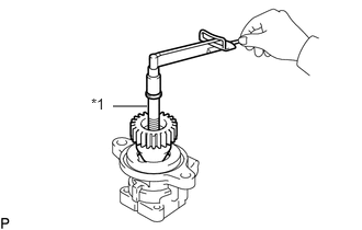
Using a torque wrench, check the pump rotating torque.
| *1 | Service Bolt |
- Torque:
0.27 N*m (2.8 kgf*cm, 2.4 in.*lbf) or less
- HINT:
-
If the result is not as specified, check that the lip of the vane pump housing oil seal is not reversed. In addition, check each part for proper installation.
Remove the service bolt.
44330
9.INSTALL FLOW CONTROL VALVE
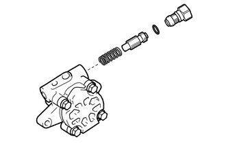
Install the spring onto the vane pump front housing.
Coat the flow control valve with power steering fluid.
Install the flow control valve onto the vane pump front housing.
- NOTICE:
-
Install the flow control valve in the correct direction.
Coat a new O-ring with power steering fluid.
Install the O-ring onto the pressure port union.
Using a socket wrench (27 mm), install the pressure port union onto the vane pump front housing.
- Torque:
69 N*m (704 kgf*cm, 51 ft.*lbf)
44337
10.INSTALL POWER STEERING SUCTION PORT UNION
Coat a new O-ring with power steering fluid.
Install the O-ring onto the suction port union.
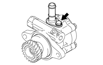
Install the suction port union onto the vane pump front housing with the bolt.
- Torque:
12 N*m (122 kgf*cm, 9 ft.*lbf)