STEERING COLUMN STEERING COLUMN ASSEMBLY DISASSEMBLY
PROCEDURE

 45204
1.REMOVE LOWER STEERING COLUMN TUBE ASSEMBLY
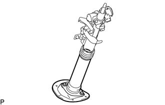
Remove the lower steering column tube assembly from the steering column tube cover.
45872
2.REMOVE STEERING COLUMN TUBE COVER
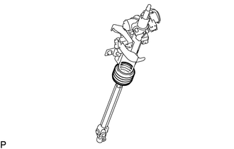
Remove the steering column tube cover from the upper steering column tube sub-assembly.
45025D
3.REMOVE NO. 1 STEERING COLUMN HOLE COVER SUB-ASSEMBLY
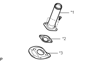
Remove the 2 bolts, lower main shaft dust cover and No. 1 steering column hole cover sub-assembly from the lower steering column tube assembly.
| *1 | Lower Steering Column Tube Assembly |
| *2 | Lower Main Shaft Dust Cover |
| *3 | No .1 Steering Column Hole Cover Sub-assembly |
4.REMOVE UPPER STEERING COLUMN WITH SWITCH BRACKET ASSEMBLY
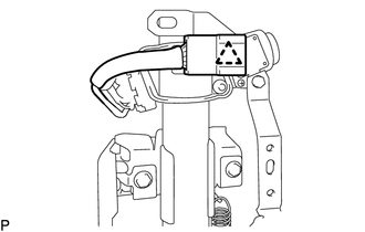
Disengage the clamp and disconnect the connector.
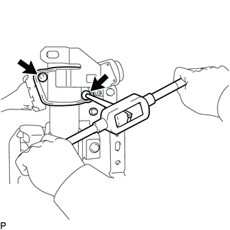
Using a 3 to 4 mm (0.118 to 0.157 in.) diameter drill bit, drill a hole in the steering lock set bolt.
Using a screw extractor, remove the 2 steering lock set bolts.
69570
5.REMOVE IGNITION SWITCH LOCK CYLINDER ASSEMBLY
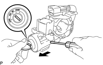
Turn the ignition switch lock cylinder to the ACC position.
Insert a screwdriver into the hole of the steering column upper with switch bracket assembly as shown in the illustration. Pull the ignition switch lock cylinder to remove it.
84450
6.REMOVE IGNITION OR STARTER SWITCH ASSEMBLY
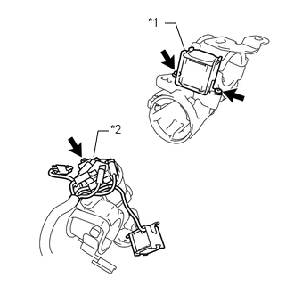
for Automatic Transmission:
Remove the 2 screws and key interlock solenoid.
| *1 | Key Interlock Solenoid |
| *2 | Ignition or Starter Switch Assembly |
Remove the screw and ignition or starter switch assembly.
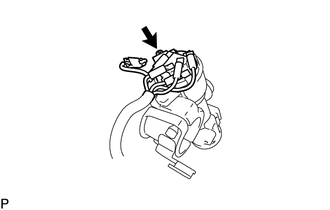
for Manual Transmission:
Remove the screw and ignition or starter switch assembly.
45210
7.REMOVE STEERING MAIN SHAFT ASSEMBLY
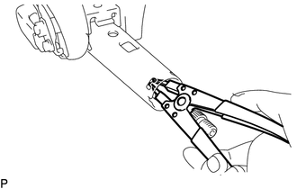
Using a snap ring expander, remove the snap ring.
Remove the steering main shaft assembly from the upper steering column tube.
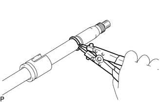
Using a snap ring expander, remove the snap ring.
45225
8.REMOVE BEARING BLOCK
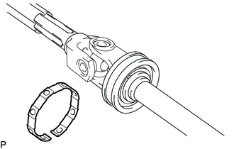
Remove the No. 1 steering column ring from the bearing block.
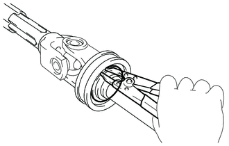
Using a snap ring expander, remove the steering main shaft ring and bearing block from the steering main shaft assembly.
45291A
9.REMOVE STEERING COLUMN TUBE SUPPORT (w/ Tilt Steering Column)
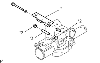
Remove the nut, 2 washers and disconnect the bolt.
| *1 | Steering Column Tube Support |
| *2 | Telescopic Steering Bush |
| *3 | Steering Tilt Retainer Collar |
Remove the steering column tube support.
Remove the 2 telescopic steering bushs and steering tilt retainer collar.
45765
10.REMOVE TELESCOPIC STEERING GUIDE (w/ Tilt Steering Column)
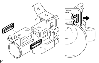
Detach the 4 claws to remove the 2 telescopic steering guides.
- NOTICE:
-
Do not damage the telescopic steering guide.
11.REMOVE TENSION SPRING (w/ Tilt Steering Column)
Remove the tension spring.
45874B
12.REMOVE NO. 1 STEERING COLUMN PROTECTOR (w/ Tilt Steering Column)
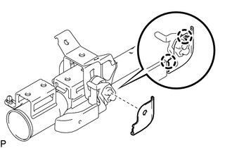
Detach the 2 claws to remove the No. 1 steering column protector.
45826
13.REMOVE STEERING TILT LEVER (w/ Tilt Steering Column)
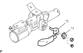
Remove the bolt and No. 1 tilt steering support Reinforcement.
| *1 | No. 1 Tilt Steering Support Reinforcement |
| *2 | Steering Tilt Lever |
Remove the nut and steering tilt lever.
45257A
14.REMOVE STEERING COLUMN ENERGY ABSORBING PLATE (w/ Tilt Steering Column)
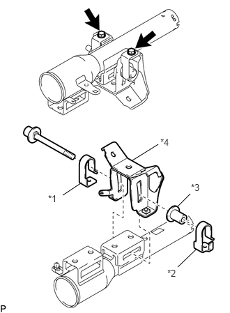
Remove the 2 bolts.
| *1 | Steering Column Energy Absorbing Plate |
| *2 | No. 2 Steering Column Energy Absorbing Plate |
| *3 | Support Collar |
| *4 | Energy Absorbing Bracket Sub-assembly |
Remove the bolt and steering column energy absorbing plate, No. 2 steering column absorbing plate, support collar and energy absorbing bracket sub-assembly.