STEERING COLUMN STEERING COLUMN ASSEMBLY REASSEMBLY
PROCEDURE

 45257A
1.INSTALL STEERING COLUMN ENERGY ABSORBING PLATE (w/ Tilt Steering Column)
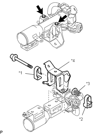
Apply MP grease to the bolt, support collar and upper steering column tube.
| *1 | Steering Column Energy Absorbing Plate |
| *2 | No. 2 Steering Column Energy Absorbing Plate |
| *3 | Support Collar |
| *4 | Energy Absorbing Bracket Sub-assembly |

|
Apply MP Grease |
Install the bolt, steering column energy absorbing plate and energy absorbing bracket sub-assembly.
Install the No. 2 steering column energy absorbing plate and support collar.
Install the energy absorbing bracket sub-assembly with the 2 bolts.
- Torque:
5.5 N*m (56 kgf*cm, 49 in.*lbf)
45826
2.INSTALL STEERING TILT LEVER (w/ Tilt Steering Column)
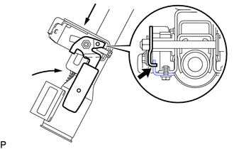
Pass the steering tilt lever through the bolt and temporarily install the adjusting nut.
Set the steering column tilt to the lowest level (toward the user) and telescopic to the most extended out level.
Align the steering tilt lever to the lock position (touching the stopper), and tighten the adjusting nut.
- Torque:
21 N*m (209 kgf*cm, 15 ft.*lbf)
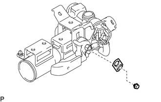
Install the No. 1 tilt steering support reinforcement with the bolt.
- Torque:
5.5 N*m (56 kgf*cm, 49 in.*lbf)
45874B
3.INSTALL NO. 1 STEERING COLUMN PROTECTOR (w/ Tilt Steering Column)
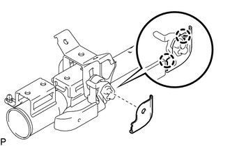
Attach the 2 claws to install the No. 1 steering column protector.
4.INSTALL TENSION SPRING (w/ Tilt Steering Column)
Install the tension spring.
45765
5.INSTALL TELESCOPIC STEERING GUIDE (w/ Tilt Steering Column)
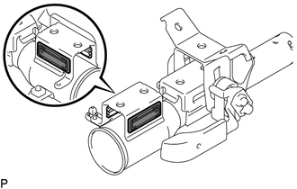
Install the 2 telescopic steering guide to the upper steering column tube.
|
|
Apply MP Grease |
Apply MP grease to the telescopic steering guide.
45291A
6.INSTALL STEERING COLUMN TUBE SUPPORT (w/ Tilt Steering Column)
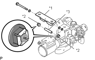
Apply MP grease to the steering column tube support.
| *1 | Steering Column Tube Support |
| *2 | Telescopic Steering Bush |
| *3 | Steering Tilt Lever Retainer Collar |
|
|
Apply MP Grease |
Install the 2 telescopic steering bush and steering tilt lever retainer collar to the upper steering column tube.
Install the steering column tube support and 2 washers with the bolt and nut.
- Torque:
5.0 N*m (51 kgf*cm, 44 in.*lbf)
- NOTICE:
- ·
Make sure to install the steering column tube support and bolt in the correct direction.
·Keep the threaded portion free from MP grease.
Check that the steering column tube support slides smoothly.
45225
7.INSTALL BEARING BLOCK
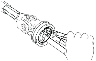
Install the bearing block to the steering main shaft assembly.
Using a snap ring expander, install a new steering main shaft ring to the steering main shaft assembly.
- NOTICE:
- ·
Do not expand steering main shaft ring too much.
·Insert steering main shaft ring correctly.
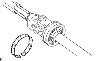
Install the No.1 steering column ring to the bearing block.
45210
8.INSTALL STEERING MAIN SHAFT ASSEMBLY
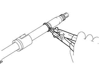
Using a snap ring expander, install a new snap ring.
- NOTICE:
- ·
Do not damage the steering main shaft assembly.
·Do not overextend the snap ring.
·Make sure that the snap ring is securely fitted into the groove.
Install the steering main shaft assembly to the upper steering column tube.
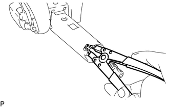
Using a snap ring expander, install a new snap ring.
- NOTICE:
- ·
Do not damage the steering main shaft assembly.
·Do not overextend the snap ring.
·Make sure that the snap ring is securely fitted into the groove.
84450
9.INSTALL IGNITION OR STARTER SWITCH ASSEMBLY
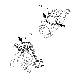
for Automatic Transmission:
Install the ignition or starter switch assembly with the screw.
| *1 | Key Interlock Solenoid |
| *2 | Ignition or Starter Switch Assembly |
Install the key interlock solenoid with the 2 screws.
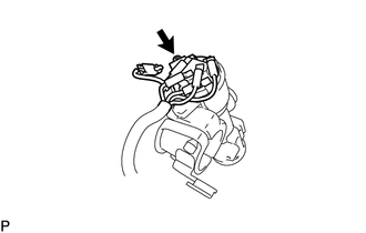
for Manual Transmission:
Install the ignition or starter switch assembly with the screw.
69570
10.INSTALL IGNITION SWITCH LOCK CYLINDER ASSEMBLY
Make sure that the ignition switch lock cylinder is in the ACC position.
Install the ignition switch lock cylinder.
Make sure that the ignition switch lock cylinder assembly is securely installed.
11.INSPECT STEERING LOCK OPERATION
Check that the steering lock mechanism is activated when removing the key.
Check that the steering lock mechanism is deactivated when inserting the key and turning to ACC position.
12.INSTALL UPPER STEERING COLUMN WITH SWITCH BRACKET ASSEMBLY
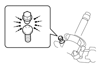
Install 2 new steering lock set bolts and tighten the 2 steering lock set bolts until the bolt head breaks off.
Engage the clamp and connect the connector.
45025D
13.INSTALL NO. 1 STEERING COLUMN HOLE COVER SUB-ASSEMBLY
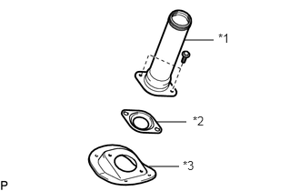
Install the lower steering column tube assembly, lower main shaft dust cover and No. 1 steering column hole cover sub-assembly with the 2 bolts.
- Torque:
12 N*m (122 kgf*cm, 9 ft.*lbf)
| *1 | Lower Steering Column Tube Assembly |
| *2 | Lower Main Shaft Dust Cover |
| *3 | No .1 Steering Column Hole Cover Sub-assembly |
45872
14.INSTALL STEERING COLUMN TUBE COVER
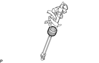
Install the steering column tube cover to the upper steering column tube.
45204
15.INSTALL LOWER STEERING COLUMN TUBE ASSEMBLY
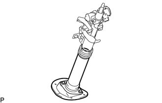
Install the lower steering column tube assembly to the steering column tube cover.