STEERING GEAR / LINKAGE STEERING GEAR REASSEMBLY
PROCEDURE

 1.INSTALL CONTROL VALVE SUB-ASSEMBLY AND BALLS
Install the dust seal to the power piston sub-assembly.
Coat a power piston with power steering fluid.
Snug the ring down for 5-7 minutes.
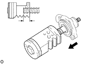
Install the control valve sub-assembly about 15mm (0.59 in.) from the power piston shaft end, and align the ball transfer surface of the power piston shaft with the ball hole of the power piston sub-assembly.
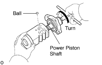
Clear the ball guide and balls with power steering fluid.
Insert the balls one at a time into the hole, and turn the power piston shaft a little with each insertion. Then securely insert the 30 balls into the power piston sub-assembly.
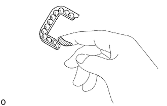
Install the 11 balls to the ball guide, and apply molybdenum disulfide lithium base grease to the ball guide lips so the balls do not fall out.
Install the guide to the power piston sub-assembly.
- NOTICE:
-
Be careful not to damage the ball guide.
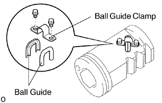
Install the ball guide clamp.
Using a socket wrench, torque the 2 bolts.
- Torque:
5.0 N*m (51 kgf*cm, 44 in.*lbf)
Check that the power piston sub-assembly rotates smoothly.
Turn the power piston shaft, and ensure that it is adhead to the tip surface of the valve housing.
- HINT:
-
If a ball has fallen out, there will be a gap.
2.INSTALL CONTROL VALVE SUB-ASSEMBLY
Mount the gear housing on SST and clamp SST in a vise.
- SST
- 09630-00015 (09631-00142)
Install the control valve assembly while holding the power piston sub-assembly by your finger.
Install the 4 bolts.
- Torque:
88 N*m (900 kgf*cm, 65 ft.*lbf)
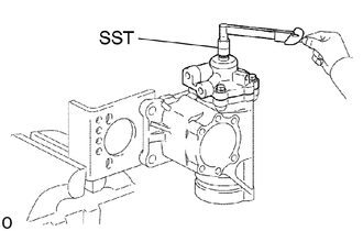
Using SST, check the power piston rotating torque.
- SST
- 09616-00010
- Rotating torque:
0.35 - 1.0 N*m (3.6 - 10 kgf*cm, 4.1 - 8.7 in.*lbf)
If the rotating torque is not within the limits or difference between clockwise and counterclockwise rotating torque is over 0.4 N*m (4 kgf*cm, 3.5 in.*lbf), replace the power piston sub-assembly.
44168
3.INSTALL WORM SHAFT DUST COVER
4.INSTALL SECTOR SHAFT AND SECTOR SHAFT SIDE COVER
Coat new O-ring and oil seal with power steering fluid.
Install the O-ring and oil seal to the side cover.
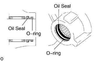
IInstall the O-ring and oil seal to the gear housing, as shown in the illustration.
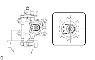
Set the power piston at the center of the shaft.
Install and push sector shaft into the gear housing so that the center teeth mesh together.
Install the 6 bolts.
- Torque:
88 N*m (900 kgf*cm, 65 ft.*lbf)
5. DETERMINE CENTER POSITION
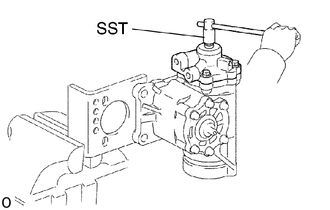
Using SST, turn the power piston shaft so full lock in both direction and determine the exact center.
- SST
- 09616-00010
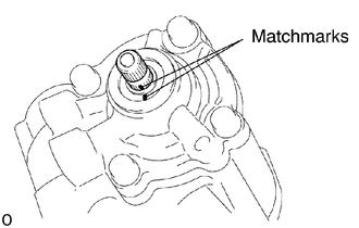
Place matchmarks on the power piston shaft and end cover of the power piston sub-assembly to show neutral position.
6.ADJUST TOTAL PRELOAD
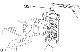
Install SST with a torque wrench in the power piston shaft.
- SST
- 09616-00010
Using a hexagon wrench, turn the sector shaft adjusting screw until the preload is within specification.
- Preload (Turning):
0.2 - 0.4 N*m (2 - 4 kgf*cm, 1.7 - 3.5 in.*lbf)
Using a hexagon wrench, hold the adjusting screw and torque the lock nut.
- Torque:
98 N*m (1,000 kgf*cm, 72 ft.*lbf)
Recheck the total preload.
- Preload (Turning):
0.2 - 0.4 N*m (2 - 4 kgf*cm, 1.7 - 3.5 in.*lbf)
45411
7.INSTALL PITMAN ARM
Align the matchmarks on the sector shaft and the pitman arm.
Install the spring washer and nut.
- Torque:
35 N*m (3,416 kgf*cm, 247 ft.*lbf)
8.INSTALL HOUSING BRACKET
Remove the SST.
Install the housing bracket with the 4 bolts.
- Torque:
185 N*m (1,886 kgf*cm, 136 ft.*lbf)