STEERING GEAR / LINKAGE STEERING LINKAGE DISASSEMBLY
PROCEDURE

 45440
1.REMOVE STEERING DRAG LINK ASSEMBLY
Secure the center arm bracket in a vise.
- NOTICE:
-
Place aluminum plates on the vise to prevent damage to the center arm bracket.
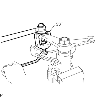
Remove the cotter pin and nut.
Using SST, remove the steering drag link assembly from the center arm bracket assembly.
- NOTICE:
-
Do not drop the steering drag link assembly.
- SST
- 09610-55012
45047
2.REMOVE TIE ROD END SUB-ASSEMBLY LH
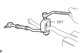
Remove the cotter pin and nut.
Using SST, remove the tie rod end sub-assembly.
- SST
- 09610-55012
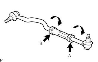
Place matchmarks on the steering tie rod and tie rod sub-assembly, and the steering tie rod and No. 2 tie rod sub-assembly.
- NOTICE:
-
When installing the tie rod end, place matchmarks to distinguish between left and right.
Remove the 2 lock nuts, steering tie rod, tie rod sub-assembly and No. 2 tie rod sub-assembly.
- NOTICE:
-
Lock nut A is a left-hand thread nut. Therefore, make sure to install in the correct direction.
45046
3.REMOVE TIE ROD END SUB-ASSEMBLY RH
- HINT:
-
Use the same procedure as for the LH side.
4. PRE-DISASSEMBLY INSPECT CENTER ARM BRACKET ASSEMBLY
45421
5.REMOVE STEERING CENTER ARM
Secure the center arm bracket in a vise.
- NOTICE:
-
Place aluminum plates on the vise to prevent damage to the center arm bracket.
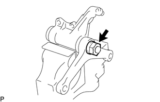
Remove the nut and washer.
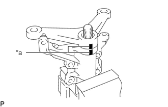
Put matchmarks on the center arm bracket and steering center arm.
| *a | Matchmark |
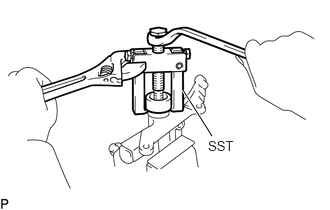
Using SST, remove the steering center arm.
- SST
- 09628-62011
45422
6.REMOVE CENTER ARM SHAFT
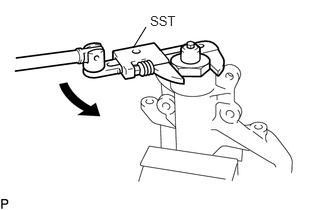
Using SST, loosen the center arm bracket cap and remove the center arm bracket cap with/ center arm shaft from the center arm bracket.
- SST
- 09922-10010
- NOTICE:
-
Be sure to use SST in the correct orientation.
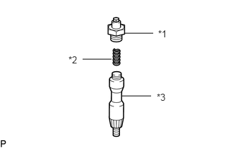
Detach the center arm bracket cap and remove the center arm shaft and compression spring.
| *1 | Center Arm Bracket Cap |
| *2 | Compression Spring |
| *3 | Center Arm Shaft |
45422D
7.REMOVE CENTER ARM SHAFT SEAL
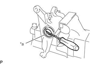
Using a screwdriver, remove the center arm shaft seal.
| *a | Protective tape |
- HINT:
-
Tape the screwdriver tip before use.
8. PRE-DISASSEMBLY INSPECT IDLER ARM BRACKET ASSEMBLY
45490
9.REMOVE STEERING IDLER ARM ASSEMBLY
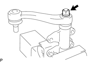
Remove the nut, washer and plate.
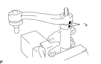
Put matchmarks on the idler arm bracket and steering idler arm assembly.
| *a | Matchmark |
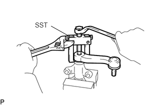
Using SST, remove the steering idler arm assembly from the idler arm shaft.
- SST
- 09628-62011
45495A
10.REMOVE IDLER ARM SHAFT
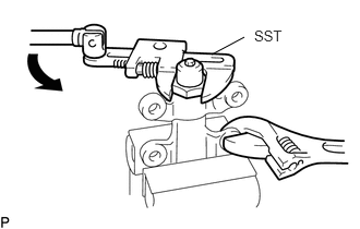
Using SST, loosen the idler arm bracket cap and remove the idler arm bracket cap with/ idler arm shaft from the idler arm bracket.
- SST
- 09922-10010
- NOTICE:
-
Be sure to use SST in the correct orientation.
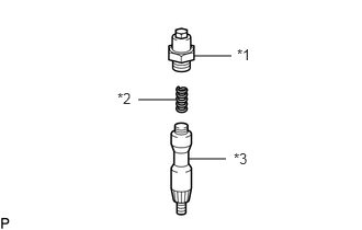
Detach the idler arm bracket cap and remove the idler arm shaft and compression spring.
| *1 | Idler Arm Bracket Cap |
| *2 | Compression Spring |
| *3 | Idler Arm Shaft |
45495B
11.REMOVE IDLER ARM SHAFT SEAL
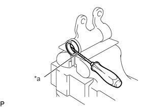
Using a screwdriver, remove the idler arm shaft seal.
| *a | Protective tape |
- HINT:
-
Tape the screwdriver tip before use.