STEERING GEAR / LINKAGE STEERING LINKAGE INSPECTION
PROCEDURE

 45440
1.INSPECT STEERING DRAG LINK ASSEMBLY
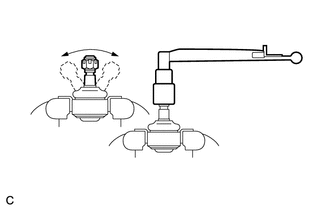
Secure the steering drag link assembly in a vise between aluminum plates.
Install the nut to the stud bolt.
Flip the ball joint back and forth 5 times.
Using a torque wrench and the nut, turn the stud bolt continuously at a rate of 2 to 4 seconds per turn, and check the turning torque on the 5th turn.
- Torque:
- Standard turning torque:
1.57 to 3.92N*m ( 16 to 40 kgf*cm , 14 to 35 in.*lbf )
If the turning torque is not within the specified range, replace the steering drag link assembly with a new one.
45047
2.INSPECT TIE ROD END SUB-ASSEMBLY LH
Secure the tie rod end sub-assembly LH in a vise between aluminum plates.
Install the nut to the stud bolt.
Flip the ball joint back and forth 5 times.
Using a torque wrench and the nut, turn the stud bolt continuously at a rate of 2 to 4 seconds per turn, and check the turning torque on the 5th turn.
- Torque:
- Standard turning torque:
1.57 to 3.92N*m ( 16 to 40 kgf*cm , 14 to 35 in.*lbf )
If the turning torque is not within the specified range, replace the tie rod end sub-assembly with a new one.
45046
3.INSPECT TIE ROD END SUB-ASSEMBLY RH
- HINT:
-
Use the same procedure as for the LH side.
45410
4.INSPECT CENTER ARM BRACKET ASSEMBLY
Center arm bracket assembly pre-disassembly inspection (bush wear inspection):
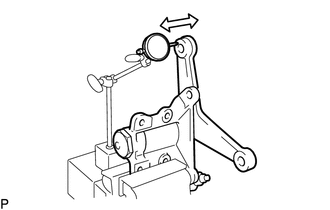
Secure the Center arm bracket in a vise.
- NOTICE:
-
Place aluminum plates on the vise to prevent damage to the Center arm bracket.
Read the dial gauge instructions when 5 kg of load is applied to the end of the center arm.
- Limit value:
0.5mm (0.0197 in.)
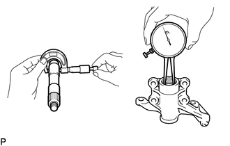
Using a micrometer and caliper gauge, measure the clearance.
- Standard value:
0.009 to 0.059 mm (0.0004 to 0.0023 in.)
- Limit value:
0.1 mm (0.004 in.)
45070
5.INSPECT IDLER ARM BRACKET ASSEMBLY
Idler arm bracket assembly pre-disassembly inspection (bush wear inspection):
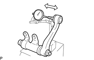
Secure the Idler arm bracket in a vise.
Read the dial gauge instructions when 5 kg of load is applied to the end of the Idler arm.
- Limit value:
0.5mm (0.0197 in.)
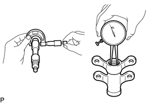
Using a micrometer and caliper gauge, measure the clearance.
- Standard value:
0.007 to 0.049 mm (0.0003 to 0.0019 in.)
- Limit value:
0.1 mm (0.004 in.)
45495A
6.INSPECT IDLER ARM SHAFT
Secure the idler arm bracket in a vise between aluminum plates.
Install the nut to the stud bolt.
Using a torque wrench and the nut, turn the stud bolt continuously at a rate of 2 to 4 seconds per turn, and check the turning torque on the 5th turn.
- Torque:
- Standard Turning Torque:
0.98 to 9.8 N*m ( 10 to 100 kgf*cm , 9 to 87in.*lbf )
If the turning torque is not within the specified range, replace the idler arm shaft with a new one.