STEERING GEAR / LINKAGE STEERING LINKAGE REASSEMBLY
PROCEDURE

 45495B
1.INSTALL IDLER ARM SHAFT SEAL
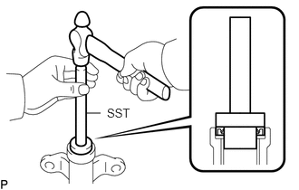
Using SST and a hammer, push in a new idler arm shaft seal so it is flush with the edge of the bracket.
- SST
- 09316-60012 (09316-00011, 09316-00021)
Apply chassis grease to the lip portion of the idler arm shaft seal.
45495A
2.INSTALL IDLER ARM SHAFT
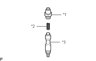
Install the compression spring and idler arm bracket cap to the idler arm shaft.
| *1 | Idler Arm Bracket Cap |
| *2 | Compression Spring |
| *3 | Idler Arm Shaft |
Apply chassis grease to the sliding parts on the idler arm shaft and idler arm bracket.
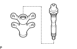
Install the idler arm bracket cap with/ idler arm shaft to the idler arm bracket.
- NOTICE:
-
Be careful not to damage the idler arm shaft seal.
45497
3.INSTALL IDLER ARM BRACKET CAP
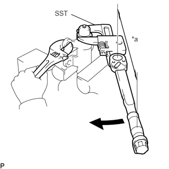
Using SST, install the idler arm bracket cap.
| *a | Torque Wrench Fulcrum Length |
- SST
- 09922-10010
- Torque:
- Specified tightening torque:
115N*m ( 1173kgf*cm , 85 ft.*lbf )
- CAUTION:
-
Be sure to use SST in the correct orientation.
- HINT:
- ·
Calculate the torque wrench reading when changing the fulcrum length of the torque wrench.
(Click hereGeneral>INTRODUCTION>REPAIR INSTRUCTION>PRECAUTION)
·When using SST (fulcrum length of 128.5 mm (5.059 in.)) + torque wrench (fulcrum length of 400 mm (15.748 in.)): 87 N*m (887 kgf*cm, 64 ft.*lbf)
45490
4.INSTALL STEERING IDLER ARM ASSEMBLY
Align the matchmarks of the idler arm bracket and steering idler arm assembly.
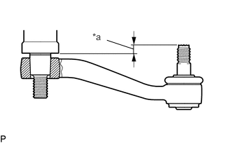
Rotate the idler arm shaft and install the steering idler arm assembly so that the clearance between the idler arm bracket and steering idler arm assembly is as specified.
| *a | 7.0 to 8.0 mm (0.276 to 0.314 in.) |
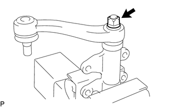
Install the plate, washer with the nut.
- Torque:
140N*m ( 1428kgf*cm , 103 ft.*lbf )
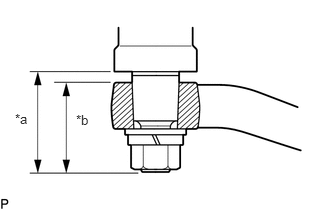
Measure each of the dimensions in the illustration.
| *a | 51.5 to 54.5 mm (2.028 to 2.145 in.) |
| *b | 45.5 to 47.5 mm (1.792 to 1.870 in.) |
5.APPLY IDLER ARM BRACKET ASSEMBLY GREESE
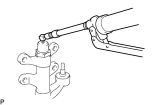
Detach the plug, remove the grease needle and fill it with chassis grease.
- Standard Grease Capacity:
30 g (1.05 oz)
Install the plug.
- Torque:
5.0N*m ( 51kgf*cm , 44in.*lbf )
45422D
6.INSTALL CENTER ARM SHAFT SEAL
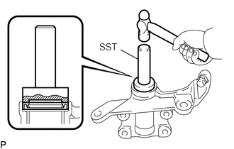
Using SST and a hammer, push in a new center arm shaft seal so it is flush with the edge of the bracket.
- SST
- 09309-14010 09316-60012 (09316-00011)
Apply chassis grease to the lip portion of the center arm shaft.
45422
7.INSTALL CENTER ARM SHAFT
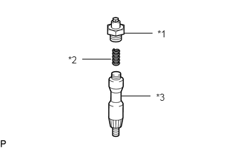
Install the compression spring and center arm bracket cap to the center arm shaft.
| *1 | Center Arm Bracket Cap |
| *2 | Compression Spring |
| *3 | Center Arm Shaft |
Apply chassis grease to the sliding parts on the center arm shaft and center arm bracket.
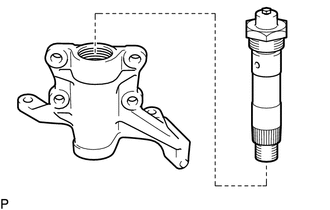
Install the center arm bracket cap with/ idler arm shaft to the center arm bracket.
- NOTICE:
-
Be careful not to damage the center arm shaft seal.
45434
8.INSTALL CENTER ARM BRACKET CAP
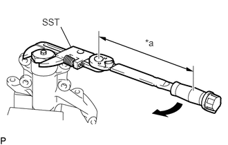
Using SST, install the center arm bracket cap.
| *a | Torque Wrench Fulcrum Length |
- SST
- 09922-10010
- Torque:
- Specified tightening torque:
165N*m ( 1683kgf*cm , 122 ft.*lbf )
- CAUTION:
-
Be sure to use SST in the correct orientation.
- HINT:
- ·
Calculate the torque wrench reading when changing the fulcrum length of the torque wrench.
(Click hereGeneral>INTRODUCTION>REPAIR INSTRUCTION>PRECAUTION)
·When using SST (fulcrum length of 121.75 mm (4.793 in.)) + torque wrench (fulcrum length of 400 mm (15.748 in.)): 127 N*m (1295 kgf*cm, 94 ft.*lbf)
45421
9.INSTALL STEERING CENTER ARM
Align the matchmarks of the center arm bracket and steering center arm.
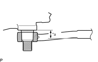
Rotate the center arm shaft and install the steering center arm so that the clearance between the center arm bracket and steering center arm is as specified.
| *a | 24.7 to 25.7 mm (0.973 to 1.011 in.) |
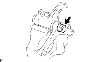
Install the washer with the nut.
- Torque:
235N*m ( 2396kgf*cm , 173 ft.*lbf )
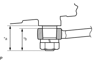
Measure each of the dimensions in the illustration.
| *a | 24.7 to 25.7 mm (0.973 to 1.011 in.) |
| *b | 54.5 to 56.5 mm (2.146 to 2.224 in.) |
10.APPLY CENTER ARM BRACKET ASSEMBLY GREESE
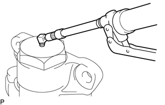
Detach the plug, remove the grease needle and fill it with chassis grease.
- Standard Grease Capacity:
35 g (1.23 oz)
Install the plug.
- Torque:
5.0N*m{ 51kgf*cm , 44in.*lbf }
45047
11.INSTALL TIE ROD END SUB-ASSEMBLY LH
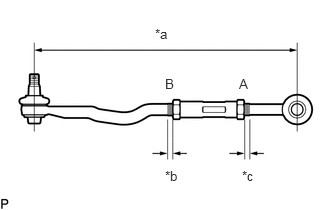
Install the steering tie rod so that its matchmarks are aligned to the tie rod sub-assembly and No. 2 tie rod sub-assembly with the 2 nuts.
- NOTICE:
-
Lock nut A is a left-hand thread nut. Therefore, make sure to install in the correct direction.
- Standard value:
Dimension A and Dimension B difference: 3.0 mm (0.119 in.)
| *a | 477.6 to 479.6 mm (18.804 to 18.881 in.) |
| *b | Dimension A |
| *c | Dimension B |
- CAUTION:
- ·
When installing the new tie rod, install at an equivalent left and right position with reference to the installation position of the old parts.
·Tighten when adjusting the toe-in.
·Ensure the amount of screw-in is the same for both nuts.
·Ensure the lengths of both tie rod assemblies is the same.
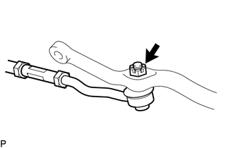
Install the tie rod end sub-assembly to the steering relay rod assembly with the nut .
- Torque:
155N*m ( 1581kgf*cm , 114 ft.*lbf )
Install a new cotter pin.
- NOTICE:
-
Further tighten the castle nut up to 60° if the hole for the cotter pin is not aligned.
45046
12.INSTALL TIE ROD END SUB-ASSEMBLY RH
- HINT:
-
Use the same procedure as for the LH side.
45440
13.CONNECT STEERING DRAG LINK ASSEMBLY
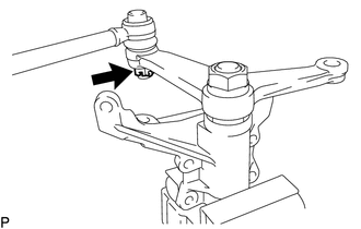
Install the steering drag link assembly to the center arm bracket assembly with the nut.
- Torque:
150N*m ( 1530kgf*cm , 111 ft.*lbf )
Install a new cotter pin.
- NOTICE:
-
Further tighten the castle nut up to 60° if the hole for the cotter pin is not aligned.