1BZ-FPE FUEL LPG REGULATOR REASSEMBLY
PROCEDURE

 1.ASSEMBLE PRIMARY DECOMPRESSING ROOM
Apply adhesive to the unions and drain cock.
- Adhesive:
Part No. 08833 - 00080, THREE BOND 1344, LOCKTITE 242 or equivalent.
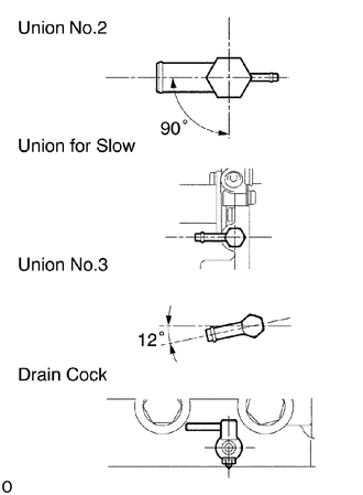
Install the 3 unions as shown in the illustration.
- Torque:
Union No.2 25 N*m (250 kgf*cm, 18 ft*lbf) or more
Union for Slow 10 N*m (100 kgf*cm, 7 ft*lbf) or more
Union No.3 10 N*m (100 kgf*cm, 7 ft*lbf) or more
Install the drain cock as shown in the illustration.
- Torque:
10 N*m (100 kgf*cm, 7 ft*lbf) or more
- NOTICE:
- ·
The union and drain cock should be placed in the correct position within one forward turn from the specified torque.
·Be careful not to give a reverse turn while tightening them.
Assemble the first valve assembly.
Install a new elastic face valve, first lever and lever pin to a new first valve seat.
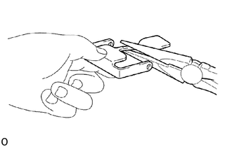
Bend the point shown in the illustration so that the valve surface can be tightly attached to the valve seat.
Install a new O-ring and the first valve assembly to the regulator body with the 2 screws.
- Torque:
3.9 N*m (40 kgf*cm, 35 in.*lbf)
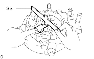
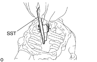
Inspect and adjust the first lever height.
Lightly pressing down the valve side of the first lever, measure the height from the upper surface of the tip of the first lever to the upper surface of the regulator body, using SST.
SST AISAN SST: 5774-31120
- Specified height:
10.7 - 11.3 mm (0.421 - 0.445 in.)
If the height is not as specified, make adjustment by bending the first lever, using SST.
- NOTICE:
- ·
Be careful not to twist the lever or apply pressure to the valve seat when bending the lever.
·When making adjustment, insert the diagonal cut of the SST to the valve side of the lever.
-
SST AISAN SST: 1000-31120 (2921-31110)
Install a new O-ring, washer, spring and idle adjust screw.
Install the stopper plate with the screw.
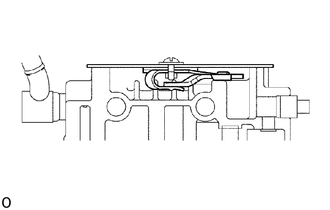
Install the first diaphragm as shown in the illustration.
Install a new O-ring to the first regulator cover.
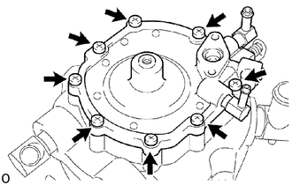
Install the spring, guide and first regulator cover with the 8 screws.
- Torque:
3.9 N*m (40 kgf*cm, 35 in.*lbf)
Install the primary pressure adjusting screw.
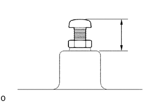
Adjust the height from the upper surface of the first regulator cover to the top of the screw.
- Standard height:
12 - 19 mm (0.47 - 0.75 in.)
Tighten the nut.
- Torque:
10 N*m (105 kgf*cm, 7 ft*lbf)
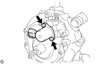
Install 2 new O-rings and the slow lock solenoid valve with the 2 screws.
- Torque:
3.9 N*m (40 kgf*cm, 35 in.*lbf)
2.ASSEMBLE SECONDARY DECOMPRESSING ROOM
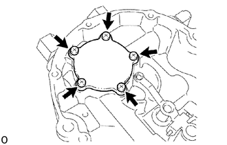
Install a new O-ring and the pre-heater cover with the 5 screws.
- Torque:
3.9 N*m (40 kgf*cm, 35 in.*lbf)
Assemble the second valve assembly.
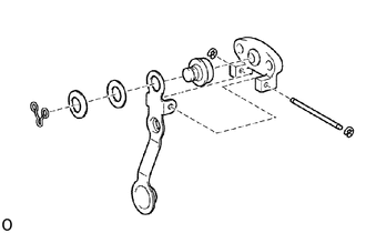
Install a new elastic face valve, washer, wave washer and retainer to the second lever.
Install a new second lever assembly, pin, and 2 new E-rings to the second valve seat.
Install a new O-ring, spring and the second valve assembly with the 2 screws.
- Torque:
3.9 N*m (40 kgf*cm, 35 in.*lbf)
Inspect the second valve airtightness.
Applying pressure between 49.0 - 53.9 kPa (0.50 - 0.55 kgf/cm2, 7.1 - 7.8 psi) to the union No.3 with SST, check for leaks.
SST AISAN SST: 1000-31120 (5901-31110)
- Standard:
No leakage for 1 minute.
If the condition is not as specified, preform (b) procedure again while turning and tilting the valve.
If the condition still does not meet the specification, replace the valve.
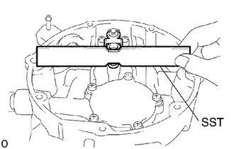
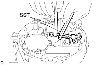
Inspect and adjust the second lever height.
Using SST, measure the height from the upper surface of the tip of the lever to the upper surface of the regulator body.
- Standard height:
1.5 - 2.0 mm (0.059 - 0.079 in.)
SST AISAN SST: 1000-31120 (5776-31110)
If the height is not as specified, make adjustment by bending the second lever, using SST.
SST AISAN SST: 1000-31120 (2921-31110, 2922-31110)
- NOTICE:
- ·
Be careful not to twist the lever or apply pressure to the valve seat when bending the lever.
·Be sure to inspect the air tightness again after adjusting the height.
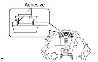
Bond the elastic face valve.
With the SST maintained still, apply the adhesive between the valve and valve lever. Wait for approx. 15 minutes to allow the valve and valve lever to be firmly bonded.
- NOTICE:
- ·
Remove the previously applied adhesive stuck on the second valve before applying the adhesive.
·Clean the attachment surface since the adhesiveness will become weaker if attachment surface is dirty or stained with oil.
·Check the airtightness and height of the lever after bonding the valve and valve lever.
Install the second diaphragm.
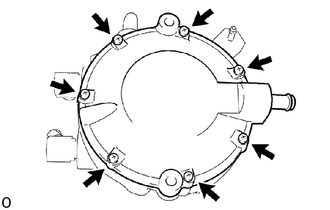
Install the second regulator cover with the 7 screws.
- Torque:
3.9 N*m (40 kgf*cm, 35 in.*lbf)
Install the fuel hose with the clips.