1BZ-FPE FUEL LPG CARBURETOR REASSEMBLY
PROCEDURE

 89452A
1.INSTALL THROTTLE POSITION SENSOR
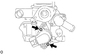
Temporarily install the throttle position sensor with the 2 screws.
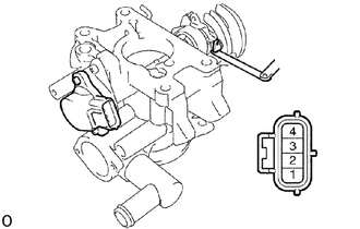
After inserting a 0.45 mm (0.0177 in.) feeler gauge between the throttle stop screw and lever, check that continuity exists between terminals 1 (E2) and 2 (IDL).
- HINT:
-
If the continuity does not exit between the terminals, turn the sensor counterclockwise until there is continuity.
Slowly turning the throttle position sensor clockwise, tighten the screw to the point where the continuity between terminals 1 and 2 dies out.
Using an ohmmeter and feeler gauge, inspect the continuity.
- Standard thickness:
0.40 mm (0.0177 in.) Continuity
0.60 mm (0.0236 in.) No continuity
If the thickness is not as specified, make adjustment by following the procedures from (b) to (d).
Fill up the slot of the screw head with yellow paint.
Inspect the resistance between terminals 3 and 2.
- Standard:
- Throttle valve full close:
0.2 - 5.9 kΩ
- Throttle valve full open:
2.3 - 10 kΩ
26214
2.INSTALL AIR ADJUST SCREW
Install the air adjust screw.
Install the plug.
- Torque:
3.9 N*m (40 kgf*cm, 35 in.*lbf)
26280
3.INSTALL AIR FUEL RATIO CONTROL MOTOR
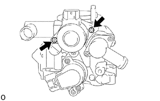
Install the air fuel ratio control motor with the 2 screws.
23260T
4.INSTALL INJECTOR
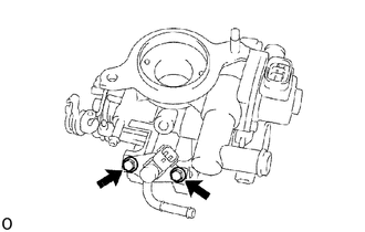
Install the injector with the 2 bolts.
- Torque:
8 N*m (80 kgf*cm, 70 in.*lbf)