1BZ-FPE STARTING STARTER REPLACEMENT
PROCEDURE

 28160
1.REPLACE FRONT BEARING
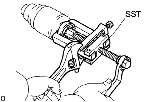
Using SST, remove the bearing.
- SST
- 09286-46011
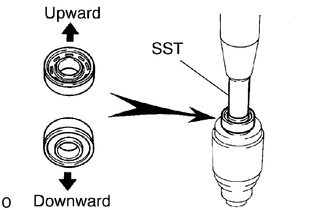
Using SST and a press, press in a new bearing.
- NOTICE:
-
Be careful of the bearing installation direction.
- SST
- 09285-76010
28160
2.REPLACE REAR BEARING
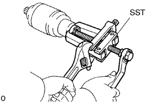
Using SST, remove the bearing.
- SST
- 09286-46011
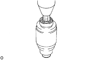
Using a press, press in a new bearing.
3.REPLACE MAGNETIC SWITCH TERMINAL KIT PARTS
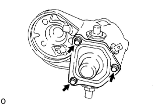
Remove the 3 bolts, end cover, gasket and plunger.
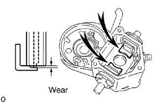
Using vernier calipers, measure the contact plate for depth of wear.
- Maximum wear:
1.6 mm (0.063 in.)
If the depth of wear is greater than the maximum, replace the contact plate.
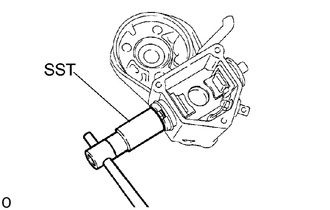
Remove the terminal kit parts.
Using SST, loosen the terminal nuts.
- SST
- 09810-38170
Terminal C:
Remove the terminal nut, wave washer, terminal insulator (outside), terminal bolt, contact plate and terminal insulator (inside).
Terminal 30:
Remove the terminal nut, wave washer, terminal insulator (outside), packing, O-ring, terminal bolt, contact plate, and terminal insulator (inside).
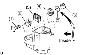
Temporarily install these new terminal C kit parts:
(1) Terminal bolt
(2) Contact plate
(3) Terminal insulator (inside)
(4) Terminal insulator (outside)
(5) Wave washer
(6) Terminal nut
- NOTICE:
-
Be careful to install the terminal insulators (inside) and wave washer in the correct direction.
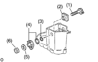
Temporarily install these new terminal 30 kit parts:
(1) Terminal bolt
(2) Terminal insulator (inside)
(3) O-ring
(4) Packing and terminal insulator (outside) Install the packing to the terminal insulator, and install them.
(5) Plate washer
(6) Terminal nut
- HINT:
-
Match the protrusion of the insulator with the indentation of the housing.
- NOTICE:
-
Be careful to install the terminal insulators (inside) in the correct direction.
Tighten terminal nuts.
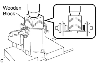
Put a wooden block on the contact plate and press it down with a hand press.
- Dimensions of wooden block:
20 x 37 x 40 mm (0.79 x 1.46 x 1.57 in.)
- Press force:
981 N (100 kgf, 221 lbf)
- NOTICE:
- ·
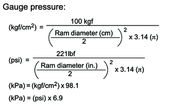
Check the diameter of the hand press ram. Then calculate the gauge pressure of the press when 981 N (100 kgf, 221 lbf) of force is applied.
·If the contact plate is not pressed down with the specified pressure, the contact plate may tilt due to coil deformation or the tightening of the nut.
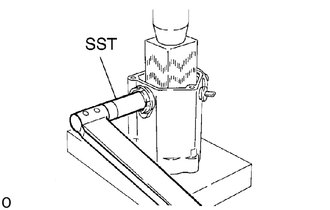
Using SST, tighten the nuts to the specified torque.
- SST
- 09810-38170
- Torque:
30 N*m (310 kgf*cm, 22 ft*lbf)
- NOTICE:
-
If the nut is over tightened, it may cause cracks on the insideof the insulator.
Clean the contact surfaces of the remaining contact plate and plunger with a dry shop rag.
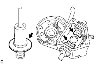
Reinstall the plunger, a new gasket and the end cover with the 3 bolts.
- Torque:
3.6 N*m (37 kgf*cm, 32 in.*lbf)