AIR CONDITIONING FRONT COOLING UNIT REASSEMBLY
CAUTION / NOTICE / HINT
- HINT:
- ·
Use the same procedure for LHD and RHD vehicles.
·The procedure listed below is for RHD vehicles.
·A bolt without a torque specification is shown in the standard bolt chart.
Click hereGeneral>SPECIFICATIONS>STANDARD BOLT>SPECIFIED TORQUE FOR STANDARD BOLTS
PROCEDURE

 88625
1.INSTALL NO. 1 COOLER THERMISTOR
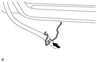
Install the clamp.
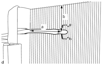
Attach the clamp to install the No. 1 cooler thermistor to the No. 1 cooler evaporator sub-assembly.
| Area | Specified Condition |
|---|---|
| a | 80 mm (3.1496 in.) |
| b | 42 mm (1.6535 in.) |
88501
2.INSTALL NO. 1 COOLER EVAPORATOR SUB-ASSEMBLY
Install the No. 1 cooler evaporator sub-assembly with the 5 bolts.
3.INSTALL LOWER COOLING UNIT CASE
Install the lower cooling unit case with the 35 screws.
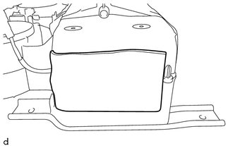
Install new packing as shown in the illustration.
88717V
4.INSTALL NO. 1 SUCTION TUBE
Remove the attached vinyl tape from the No. 1 suction tube.
Apply sufficient compressor oil (ND-OIL 8) to a new O-ring and the fitting surface of the cooler unit assembly.
Install the O-ring onto the No. 1 suction tube.
- NOTICE:
-
Keep the O-ring and O-ring fitting surfaces clean from dirt or any foreign objects.
Tighten the No. 1 suction tube onto the cooler unit assembly with the union nut.
- NOTICE:
-
Do not apply excessive force to the No. 1 suction tube.
- Torque:
42 N*m (428 kgf*cm, 31 ft.*lbf)
88515
5.INSTALL COOLER EXPANSION VALVE
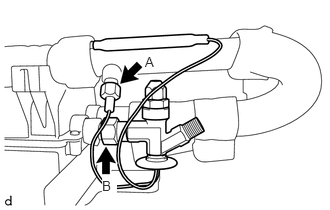
Remove the attached vinyl tape from the cooler expansion valve.
Apply sufficient compressor oil (ND-OIL 8) to a new O-ring and the fitting surface of the cooler unit assembly.
Install the 2 O-rings onto the cooler expansion valve.
- NOTICE:
-
Keep the O-ring and O-ring fitting surfaces clean from dirt or any foreign objects.
Tighten the cooler expansion valve onto the cooler unit assembly with the 2 union nuts.
- NOTICE:
-
Do not apply excessive force to the cooler expansion valve.
- Torque:
- Union Nut A:
11 N*m (112 kgf*cm, 8 ft.*lbf)
- Union Nut B:
23 N*m (235 kgf*cm, 17 ft.*lbf)
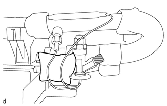
Install new packing as shown in the illustration.
88716Z
6.INSTALL NO. 1 LIQUID TUBE
Remove the attached vinyl tape from the No. 1 liquid tube.
Apply sufficient compressor oil (ND-OIL 8) to a new O-ring and the fitting surface of the cooler unit assembly.
Install the O-ring onto the No. 1 liquid tube.
- NOTICE:
-
Keep the O-ring and O-ring fitting surfaces clean from dirt or any foreign objects.
Tighten the No. 1 liquid tube onto the cooler unit assembly with the union nut.
- NOTICE:
-
Do not apply excessive force to the No. 1 liquid tube.
- Torque:
14 N*m (142 kgf*cm, 10 ft.*lbf)
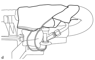
Install new packing as shown in the illustration.
Install the dust cover with the 2 screws.
87138C
7.INSTALL BLOWER RESISTOR
Install the 4 blower resistors with the 8 screws.
87103B
8.INSTALL BLOWER MOTOR WITH FAN SUB-ASSEMBLY
Install the 4 blower motor with fan sub-assemblies with the 12 screws.
88605
9.INSTALL NO. 1 COOLER WIRING HARNESS SUB-ASSEMBLY
Attach each clamps, connect each connectors to connect the No. 1 cooler wiring harness sub-assembly.
Install the 6 screws.
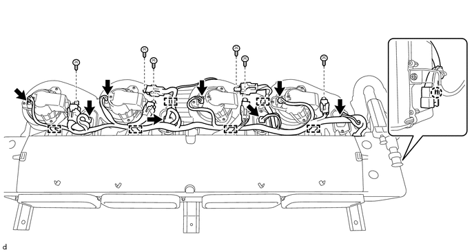
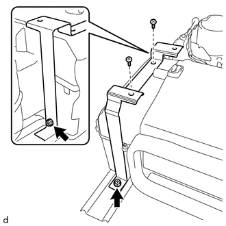
Install the cooling unit case plate LH with the 2 bolts and 2 screws.
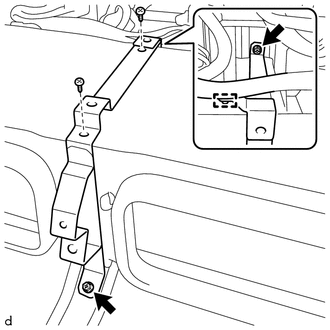
Attach the clamp.
Install the cooling unit case plate center with the 2 bolts and 2 screws.
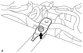
Install the bracket with the bolt.
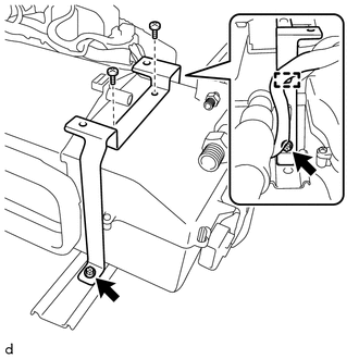
Attach the clamp.
Install the cooling unit case plate RH with the 2 bolts and 2 screws.