AIR CONDITIONING AIR CONDITIONING PANEL INSPECTION
PROCEDURE

 84660H
1.INSPECT COOLER CONTROL SWITCH ASSEMBLY (w/ Cooler System)
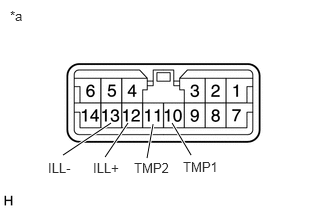
w/ Manual Air Conditioning System:
Check temperature control switch resistance
Measure the resistance according to the value(s) in the table below.
| Tester Connection | Switch Condition | Specified Condition |
|---|---|---|
| 10(TMP1) - 11(TMP2) | OFF | approximately 3 kW |
| 10(TMP1) - 11(TMP2) | MAX COLD | approximately 0 W |
- HINT:
-
Check that the resistance changes continuously between OFF and MAX HOT.
Check that the cooler control switch assembly illuminates.
Apply battery voltage to the heater blower switch and check that the illumination comes on.
| Measurement Condition | Specified Condition |
|---|---|
| Battery positive (+) → 12(ILL+)
Battery negative (-) → 13(ILL-) |
illumination comes on |
| *a | Component without harness connected
(Cooler Control Switch Assembly) |
84732E
2.INSPECT COOLER BLOWER SWITCH (w/ Cooler System)
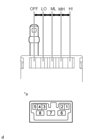
Check the cooler blower switch resistance.
Measure the resistance according to the value(s) in the table below.
| *a | Component without harness connected
(Cooler Blower Switch) |
| Tester Connection | Switch Condition | Specified Condition |
|---|---|---|
| ALL - 8 | OFF | 10 kW or higher |
| 5 - 8 | LO | Below 1 W |
| 2 - 5 - 8 | ML | Below 1 W |
| 1 - 5 - 8 | MH | Below 1 W |
| 6 - 5 - 8 | HI | Below 1 W |
If the result is not as specified, replace the cooler blower switch.
84732H
3.INSPECT HEATER BLOWER SWITCH (w/ Front Heater System)
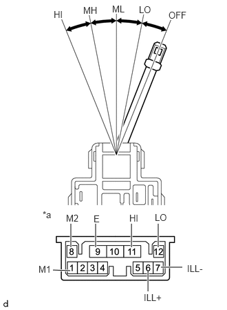
Check the heater blower switch resistance.
Measure the resistance according to the value(s) in the table below.
| *a | Component without harness connected
(Heater Blower Switch) |
| Tester Connection | Switch Condition | Specified Condition |
|---|---|---|
| ALL - 9(E) | OFF | 10 kW or higher |
| 12(LO) - 9(E) | LO | Below 1 W |
| 1(M1) - 12(LO) - 9(E) | ML | Below 1 W |
| 8(M2) - 12(LO) - 9(E) | MH | Below 1 W |
| 11(HI) - 12(LO) - 9(E) | HI | Below 1 W |
If the result is not as specified, replace the heater blower switch.
Check that the heater blower switch illuminates.
Apply battery voltage to the heater blower switch and check that the illumination comes on.
| Measurement Condition | Specified Condition |
|---|---|
| Battery positive (+) → 6(ILL+)
Battery negative (-) → 7(ILL-) |
illumination comes on |
If the result is not as specified, replace the bulb.
84732L
4.INSPECT REAR HEATER BLOWER SWITCH (w/ Rear Heater System)
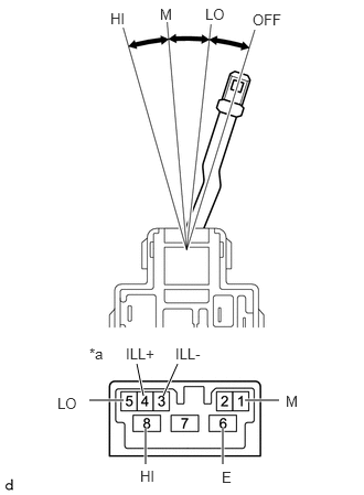
Check the rear heater blower switch resistance.
Measure the resistance according to the value(s) in the table below.
| *a | Component without harness connected
(Rear Heater Blower Switch) |
| Tester Connection | Switch Condition | Specified Condition |
|---|---|---|
| ALL - 6(E) | 0 (OFF) | 10 kW or higher |
| 5(LO) - 6(E) | LO | Below 1 W |
| 1(M) - 5(LO) - 6(E) | M | Below 1 W |
| 8(HI) - 5(LO) - 6(E) | HI | Below 1 W |
If the result is not as specified, replace the rear heater blower switch.
Check that the rear heater blower switch illuminates.
Apply battery voltage to the heater blower switch and check that the illumination comes on.
| Measurement Condition | Specified Condition |
|---|---|
| Battery positive (+) → 4(ILL+)
Battery negative (-) → 3(ILL-) |
illumination comes on |
If the result is not as specified, replace the bulb.