AIR CONDITIONING AIR CONDITIONING PANEL REASSEMBLY
CAUTION / NOTICE / HINT
- HINT:
- ·
Use the same procedure for LHD and RHD vehicles.
·The procedure listed below is for RHD vehicles.
PROCEDURE

 84732N
1.INSTALL REAR HEATER BLOWER SWITCH BULB (w/ Rear Heater System)
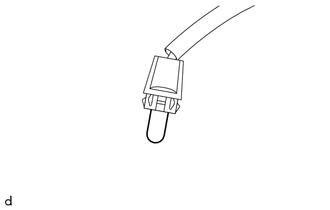
Install the rear heater blower switch bulb.
84732K
2.INSTALL HEATER BLOWER SWITCH BULB (w/ Front Heater System)
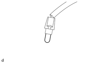
Install the heater blower switch bulb.
81936B
3.INSTALL COOLER CONTROL BULB ASSEMBLY
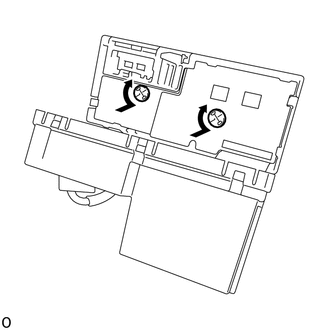
Rotate and install the 2 cooler control bulb assemblies.
84732E
4.INSTALL COOLER BLOWER SWITCH (w/ Cooler System)
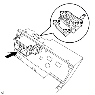
Attach the claw and 4 guides to install the cooler blower switch.
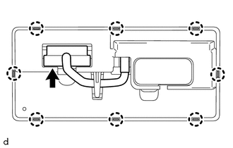
Attach the 8 claws to install the cooler control switch assembly of the cover.
Connect the connector.
84660H
5.INSTALL COOLER CONTROL SWITCH ASSEMBLY (w/ Cooler System)
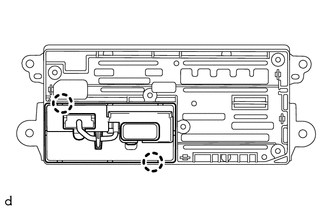
Attach the 2 claws to install the cooler control switch assembly.
84732L
6.INSTALL REAR HEATER BLOWER SWITCH (w/ Rear Heater System)
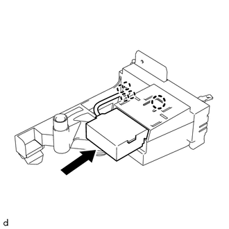
Attach the claw to install the rear heater blower switch.
Attach the 4 claws and connect the bulb socket of the cooler control switch assembly.
55906A
7.INSTALL DEFROSTER DAMPER CONTROL CABLE SUB-ASSEMBLY
Install the end of the defroster damper control cable sub-assembly inner cable to the defroster damper control lever.
Attach the claw on the clamp of the defroster damper control cable sub-assembly and install the defroster damper control cable sub-assembly to the clamp.
- NOTICE:
-
Operate the defroster damper control lever and check that there is a sense of moderation on both ends of FACE - DEF and that there is no return.
55909A
8.INSTALL AIR MIX DAMPER CONTROL CABLE SUB-ASSEMBLY
Install the end of the air mix damper control cable sub-assembly inner cable to the air mix damper control lever.
Attach the claw on the clamp of the air mix damper control cable sub-assembly and install the air mix damper control cable sub-assembly to the clamp.
- NOTICE:
-
Operate the air mix damper control lever and check that there is a sense of moderation on both ends of MAX COOL - MAX HOT and that there is no return.
84732H
9.INSTALL HEATER BLOWER SWITCH (w/ Front Heater System)
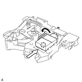
Attach the claw to install the heater blower switch.
Connect the heater blower switch bulb socket by turning it in the direction of the black arrow shown in the illustration.
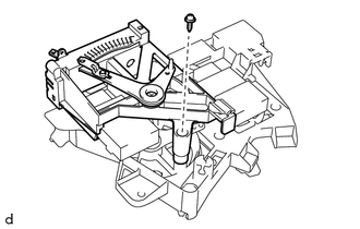
Install the screw.
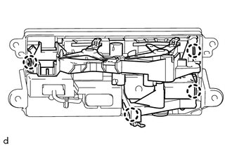
Attach the 4 claws to install the base plate.
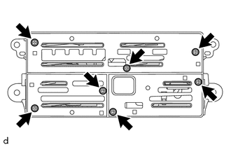
Install the 7 screws.
55519
10.INSTALL HEATER CONTROL NAME PLATE
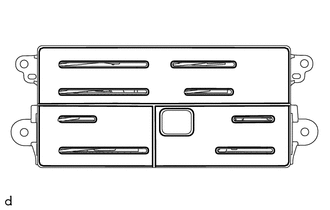
Using a heat light, heat the air conditioner control assembly surface.
| Item | Temperature |
|---|---|
| Air Conditioner Control Assembly | 20 to 30°C (68 to 86°F) |
- NOTICE:
-
Do not heat the air conditioner control assembly excessively.
Remove any double-sided tape from the air conditioner control assembly.
Wipe off any tape adhesive residue with cleaner.
Remove the release paper from the heater control name plate.
- NOTICE:
-
After removing the release paper, keep the exposed adhesive free from foreign matter.
Install new heater control name plates as shown in the illustration.
55905J
11.INSTALL CONTROL KNOB SUB-ASSEMBLY
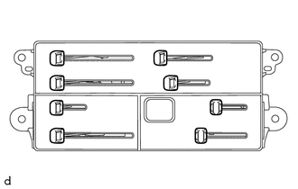
Install the control knob sub-assemblies.