RM2850E
_58
Vehicle Interior
_073208
LIGHTING
_0356323
HAZARD WARNING SWITCH
G
LIGHTING HAZARD WARNING SWITCH INSPECTION
PROCEDURE

 84330
1.INSPECT HAZARD WARNING SIGNAL SWITCH ASSEMBLY
a.
1.573,1.75 1.375,1.354
true
2.271,1.76 2.073,1.365
true
0.146,0.115 0.521,0.365
0.375,0.25
10
false
*a
1.583,1.781 1.958,2.031
0.375,0.25
10
false
F
2.25,1.792 2.625,2.042
0.375,0.25
10
false
B2
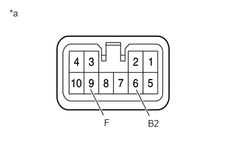
Inspect the hazard warning signal switch assembly.
Measure the resistance according to the value(s) in the table below.
- Standard Resistance:
Tester Connection Switch Condition Specified Condition 13 (T) - 1 (EL) Hazard warning signal switch off 10 kΩ or higher Hazard warning signal switch on Below 1 Ω
If the result is not as specified, replace the hazard warning signal switch assembly.
| *a | Component without harness connected
(Hazard Warning Signal Switch Assembly) |
b.
1.344,0.844 1.146,0.448
true
2.271,0.469 2.083,0.833
true
0.146,0.115 0.521,0.365
0.375,0.25
10
false
*a
0.844,0.323 1.219,0.573
0.375,0.25
10
false
ILL-
2.313,0.333 2.75,0.521
0.438,0.188
10
false
ILL+
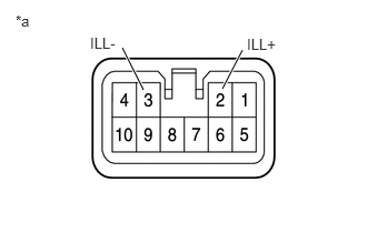
Check the illumination.
Apply battery voltage to the connector and check the illumination conditions.
- OK:
Battery Connection Specified Condition Positive → 2(ILL+)
Negative → 3(ILL-)Illuminates
If the result is not as specified, replace the hazard warning signal switch assembly.
| *a | Component without harness connected
(Hazard Warning Signal Switch Assembly) |