ENGINE HOOD / DOOR BACK DOOR(for Emergency Door) ADJUSTMENT
PROCEDURE

 67005D
1.INSPECT BACK DOOR PANEL SUB-ASSEMBLY RH
Check that the clearance measurements of areas A to F are within the standard range.
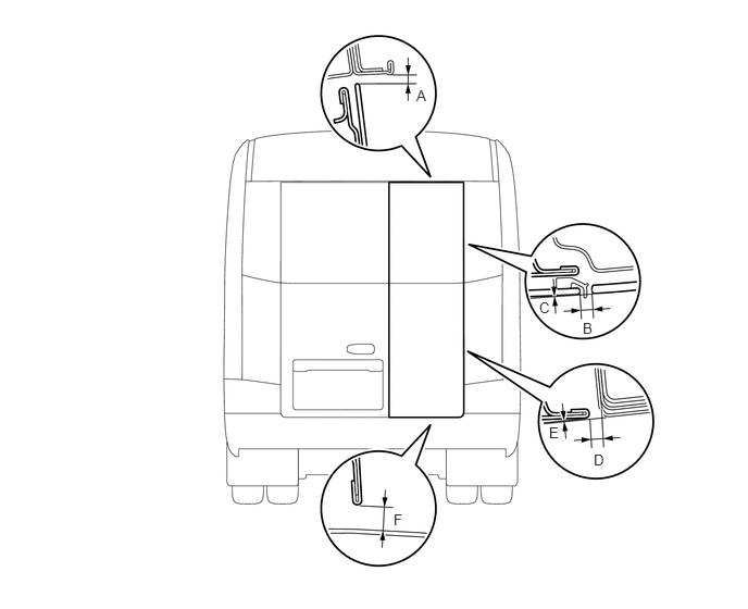
| Area | Specified Condition | Area | Specified Condition |
|---|---|---|---|
| A | 3.9 to 8.9 mm (0.154 to 0.350 in.) | B | 2.5 to 9.5 mm (0.098 to 0.374 in.) |
| C | -3.4 to 3.6 mm (-0.134 to 0.142 in.) | D | 4.5 to 7.5 mm (0.177 to 0.295 in.) |
| E | -1.4 to 1.6 mm (0.055 to 0.063 in.) | F | 7.5 to 13.5 mm (0.295 to 0.531 in.) |
67005D
2.ADJUST BACK DOOR PANEL SUB-ASSEMBLY RH
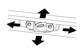
Loosen the back door upper lock striker and adjust the door's position.
Tighten the striker bolts on the door after the adjustment.
- Torque:
24 N*m (245 kgf*cm, 18 ft.*lbf)
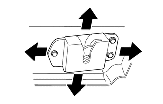
Loosen the lower back door lock assembly and adjust the door's position.
Tighten the back door lock bolts on the door after the adjustment.
- Torque:
7.5 N*m (76 kgf*cm, 66 in.*lbf)
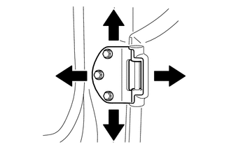
Loosen the back door hinge sub-assembly and adjust the door's position.
Tighten the hinge bolts on the door after the adjustment.
- Torque:
24 N*m (245 kgf*cm, 18 ft.*lbf)
67006A
3.INSPECT BACK DOOR PANEL SUB-ASSEMBLY LH
Check that the clearance measurements of areas A to H are within the standard range.
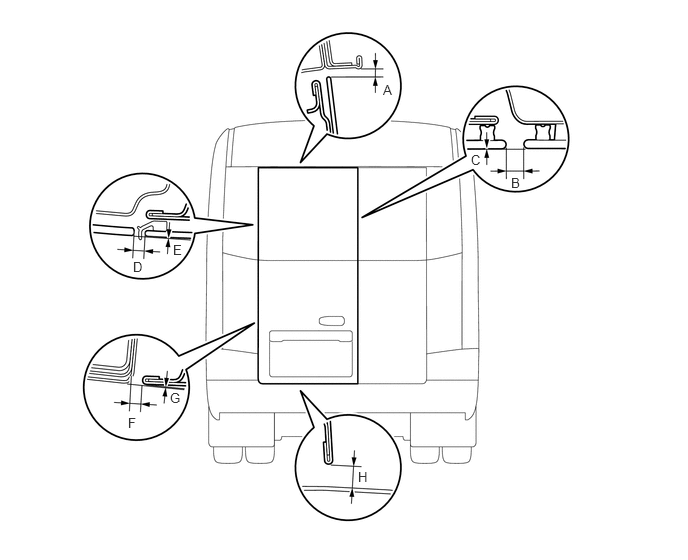
| Area | Specified Condition | Area | Specified Condition |
|---|---|---|---|
| A | 3.9 to 8.9 mm (0.154 to 0.350 in.) | B | 3.0 to 11.0 mm (0.118 to 0.433 in.) |
| C | -4.0 to 4.0 mm (-0.157 to 0.157 in.) | D | 2.5 to 9.5 mm (0.098 to 0.374 in.) |
| E | -3.5 to 3.5 mm (-0.138 to 0.138 in.) | F | 4.5 to 7.5 mm (0.177 to 0.295 in.) |
| G | -1.4 to 1.6 mm (0.055 to 0.063 in.) | H | 7.5 to 13.5 mm (0.295 to 0.531 in.) |
67006A
4.ADJUST BACK DOOR PANEL SUB-ASSEMBLY LH
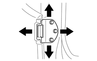
Loosen the back door hinge sub-assembly and adjust the door's position.
Tighten the hinge bolts on the door after the adjustment.
- Torque:
24 N*m (245 kgf*cm, 18 ft.*lbf)
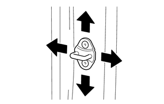
Using a T40 "TORX" socket wrench, adjust the striker position by slightly loosening the striker mounting screws and hitting the striker with a brass bar and hammer.
Using a T40 "TORX" socket wrench, tighten the striker mounting screws after the adjustment.
- Torque:
12 N*m (122 kgf*cm, 9 ft.*lbf)