ENGINE HOOD / DOOR CENTER DOOR(for Glide Type) ADJUSTMENT
CAUTION / NOTICE / HINT
- HINT:
- ·
Use the same procedure for RHD and LHD vehicles.
·The procedure listed below is for LHD vehicles.
PROCEDURE

 67003F
1.INSPECT CENTER DOOR PANEL
Check that the clearance measurements of areas A to C are within the standard range.
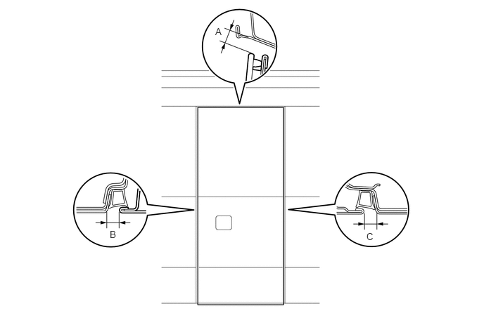
- Standard:
Area Measurement Condition Specified Condition A 2 Coat Application 6.6 to 12.6 mm (0.260 to 0.496 in.) 4 Coat Application 6.5 to 12.5 mm (0.256 to 0.492 in.) B 2 Coat Application 13.4 to 17.4mm (0.528 to 0.685 in.) 4 Coat Application 13.4 to 17.4mm (0.528 to 0.685 in.) C 2 Coat Application 13.4 to 17.4mm (0.528 to 0.685 in.) 4 Coat Application 13.3 to 17.3mm (0.524 to 0.681 in.)
67003F
2.ADJUST CENTER DOOR PANEL
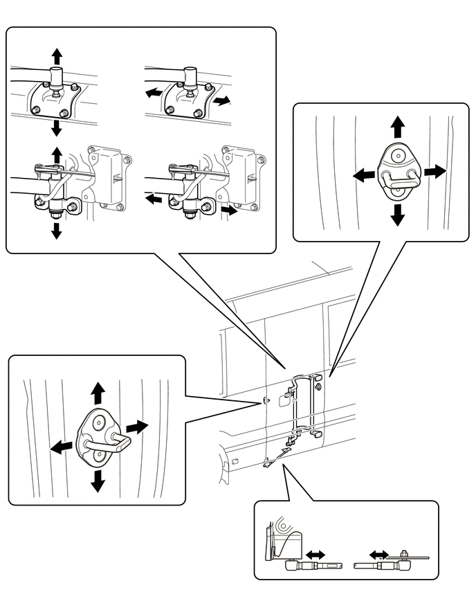
Loosen the glide door arm bracket link bolt and adjust the horizontal axis of the bottom of the door.
Tighten the glide door arm bracket link bolt after the adjustment.
- Torque:
- Upper side:
12 N*m (122 kgf*cm, 9 ft.*lbf)
- Lower side:
18 N*m (184 kgf*cm, 13 ft.*lbf)
Loosen the glide door link nut and adjust the horizontal axis of the bottom of the door.
Tighten the glide door link nut after the adjustment.
- Torque:
24.5 N*m (250 kgf*cm, 18 ft.*lbf)
Using a T40 "TORX" socket wrench, adjust the striker position by slightly loosening the striker mounting screws and hitting the striker with a brass bar and hammer.
Tighten the striker mounting screws on the body after the adjustment.
- Torque:
12 N*m (122 kgf*cm, 9 ft.*lbf)