ENGINE HOOD / DOOR CENTER DOOR(for Glide Type) REASSEMBLY
CAUTION / NOTICE / HINT
- HINT:
- ·
Use the same procedure for RHD and LHD vehicles.
·The procedure listed below is for LHD vehicles.
PROCEDURE

 84231A
1.INSTALL COURTESY LIGHT SWITCH
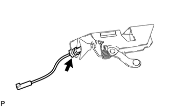
Install the courtesy light switch with nut.
69340A
2.INSTALL REAR GLIDE DOOR LOCK ASSEMBLY
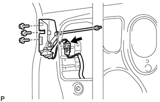
Apply MP grease to the sliding parts of the rear glide door lock assembly.
Install the rear glide door lock assembly with the 3 bolts.
- Torque:
7.5 N*m (76 kgf*cm, 66 in.*lbf)
Connect the connector.
69630A
3.INSTALL GLIDE DOOR LOCK REMOTE CONTROL ASSEMBLY
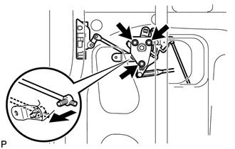
Apply MP grease to the sliding parts of the glide door lock remote control assembly.
Install the glide door lock remote control assembly with the 3 bolts.
- Torque:
5.0 N*m (51 kgf*cm, 44 in.*lbf)
Install the link.
85450A
4.INSTALL DOOR CONTROL MOTOR ASSEMBLY
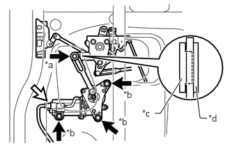
Apply MP grease to the sliding parts of the door control motor assembly and install with the 3 bolts <B>.
Install the spacer and washer with the bolt <A>.
- Torque:
5.0 N*m (51 kgf*cm, 44 in.*lbf)
Connect the connector.
| *a | Bolt <A> |
| *b | Bolt <B> |
| *c | Spacer |
| *d | Washer |

|
Bolt |

|
Connector |
69330B
5.INSTALL FRONT GLIDE DOOR LOCK ASSEMBLY
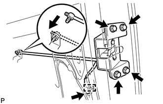
Apply MP grease to the sliding parts of the front glide door lock assembly.
Install the front glide door lock assembly with the 4 bolts.
- Torque:
7.5 N*m (76 kgf*cm, 66 in.*lbf)
Install the link.
Connect the clamp and connector.
69530E
6.INSTALL GLIDE DOOR LOCK CYLINDER ASSEMBLY
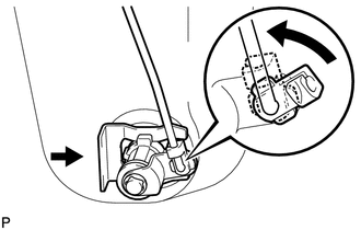
Apply MP grease to the sliding parts of the glide door lock cylinder assembly.
Install the glide door lock cylinder assembly with the retainer.
Install the link.
69751C
7.INSTALL GLIDE DOOR DOOR LOCK CONTROL KNOB HOLDER
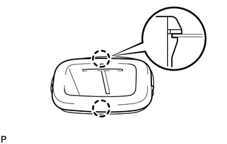
Attach the 2 claws and install the glide door door lock control knob holder.
69701D
8.INSTALL UPPER DOOR LOCK CONTROL BELLCRANK SUB-ASSEMBLY
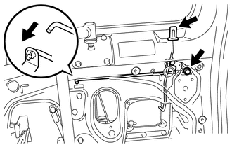
Apply MP grease to the sliding parts of the upper door lock control bellcrank sub-assembly.
Attach the guide and install the upper door lock control bellcrank with the bolt.
- Torque:
5.0 N*m (51 kgf*cm, 44 in.*lbf)
Install the door control knob.
Install the link.
69230A
9.INSTALL GLIDE DOOR OUTSIDE HANDLE ASSEMBLY
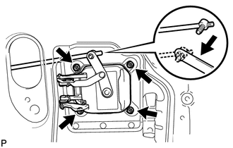
Apply MP grease to the sliding parts of the glide door outside handle assembly.
Install the glide door outside handle assembly with the 4 screws.
Install the link.
69290E
10.INSTALL GLIDE DOOR INSIDE HANDLE BASE ASSEMBLY
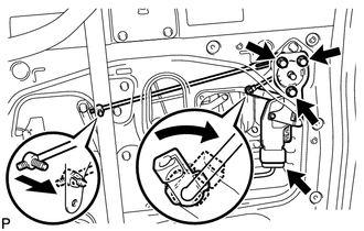
Apply MP grease to the sliding parts of the glide door inside handle base assembly.
Install the glide door inside handle base assembly with the 3 bolts.
- Torque:
5.0 N*m (51 kgf*cm, 44 in.*lbf)
Install the 2 links.
Connect the connector.
68630B
11.INSTALL GLIDE DOOR CHECK ASSEMBLY
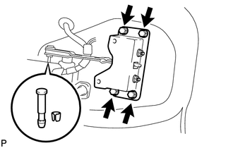
Apply MP grease to the sliding parts of the glide door check assembly.
Install the glide door check assembly with the 4 bolts.
- Torque:
18 N*m (184 kgf*cm, 13 ft.*lbf)
Install the glide door check pin and new door check pin retainer.
67841A
12.INSTALL GLIDE DOOR SERVICE HOLE COVER
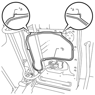
Apply new butyl tape to the door panel, and then install a new glide door service hole cover as shown in the illustration.
| *a | Reference point |
| *b | Butyl tape |
- HINT:
- ·
There should be no wrinkles or folds after attaching the glide door service hole cover.
·After attaching the service hole cover, check the quality of the seal.
67690
13.INSTALL LOWER GLIDE DOOR TRIM ASSEMBLY
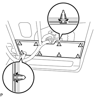
Attach the 8 clips and install the lower glide door trim assembly.
67680A
14.INSTALL GRIDE DOOR TRIM ASSEMBLY
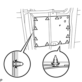
Attach the 11 clips and install the glide door trim assembly.
69281
15.INSTALL GLIDE DOOR INSIDE HANDLE
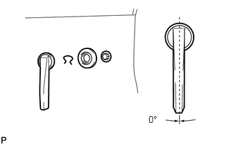
Install the plate.
Install the glide door inside handle with snap ring at the angle shown in the illustration.
69207S
16.INSTALL REAR DOOR INSIDE HANDLE COVER
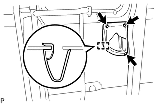
Attach the guide.
Install the rear door inside handle cover with the 3 bolts.
- Torque:
5.0 N*m (51 kgf*cm, 44 in.*lbf)