RM2850E
_54
Brake
_073226
BRAKE SYSTEM (OTHER)
_0356438
BRAKE PEDAL(w/ Brake pedal Load Sensing Switch)
G
BRAKE SYSTEM (OTHER) BRAKE PEDAL(w/ Brake pedal Load Sensing Switch) ON-VEHICLE INSPECTION
PROCEDURE

 1.INSPECT BRAKE PEDAL LOAD SENSING SWITCH
- HINT:
- ·
Do not remove the brake pedal load sensing switch from the brake pedal lever subassembly.
·When there is a malfunction in the brake pedal load sensing switch, replace the brake pedal lever sub-assembly.
a.
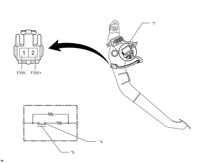
Disconnect the brake pedal load sensing switch connector.
4.615,1.542 5.104,0.823
5.104,0.823 5.375,0.823
true
1.635,4.427 3.115,5.063
3.115,5.063 3.448,5.063
true
1.49,4.521 2.188,5.448
2.188,5.448 2.49,5.448
true
0.781,2.5 0.781,1.979
true
1.26,2.5 1.26,1.979
true
0.604,2.521 1.063,2.719
0.458,0.198
10
false
FSW-
1.104,2.521 1.563,2.719
0.458,0.198
10
false
FSW+
3.552,4.979 3.792,5.198
0.24,0.219
10
false
*a
2.542,5.365 2.781,5.583
0.24,0.219
10
false
*b
5.448,0.75 5.688,0.969
0.24,0.219
10
false
*1
| *1 | Brake Pedal Load Sensing Switch | - | - |
| *a | Brake pedal released (ON) | *b | Brake pedal depressed (OFF) |
b.
Measure the resistance according to the value(s) in the table below.
- Standard Resistance:
Tester Connection Condition Specified Condition 2 (FSW+) - 1 (FSW-) Brake pedal depressed 950 to 1050 Ω Brake pedal released 203 to 223 Ω