BRAKE SYSTEM (OTHER) LOAD SENSING PROPORTIONING VALVE DISASSEMBLY
PROCEDURE

 1.REMOVE LOAD SENSING PROPORTIONING VALVE
Fix the load sensing valve bracket in a vise between aluminum plates.
- NOTICE:
-
Do not overtighten the vise.
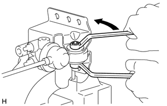
Remove the nut and washer while holding the bolt.
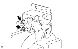
Remove the 2 nuts, 2 washers and load sensing valve set plate.
Remove the load sensing proportioning valve and 2 plate washers from the load sensing valve bracket.
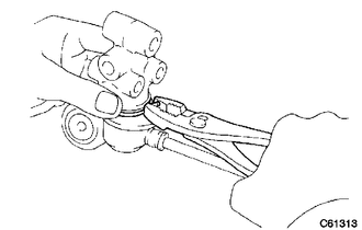
Remove the clip and load sensing proportioning valve.
2.REMOVE LOAD SENSING SPRING BUSH AND BOOT KIT
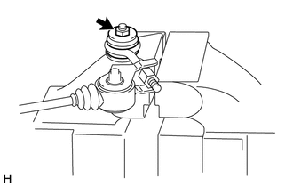
Fix the No. 1 load sensing shackle bracket in a vise between aluminum plates.
- NOTICE:
-
Do not overtighten the vise.
Remove the nut, plate washer and No. 1 load sensing shackle bracket from the No. 2 load sensing spring shackle.
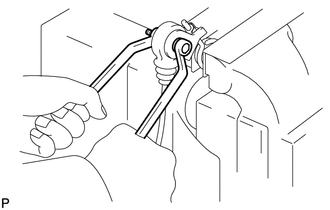
Remove the nut and washer while holding the bolt.
Remove the No. 1 load sensing spring shackle and 2 plate washers.
Remove the collar and 2 load sensing valve bushes from the No. 2 load sensing spring shackle.
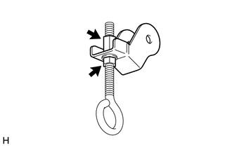
Remove the lock nut, No. 1 load sensing spring shackle, plate washer and nut from the No. 2 load sensing spring shackle.
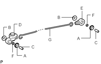
Remove the following parts from the load sensing spring.
| Symbol | Name | Quantity |
|---|---|---|
| A | No. 1 load sensing spring bush | 2 |
| B | No. 2 load sensing spring bush | 2 |
| C | Collar | 2 |
| D | Load sensing valve boot | 1 |
| E | Load sensing spring boot | 1 |
| F | Plate washer | 2 |
| G | Load sensing spring | 1 |
3.INSPECT LOAD SENSING PROPORTIONING VALVE
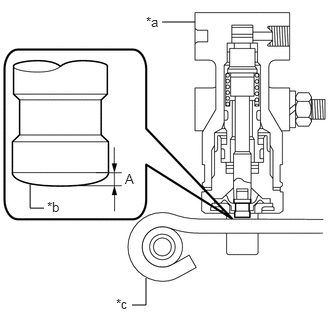
Inspect contact surface wear between the control valve piston and load sensing spring.
| *a | Load sensing proportioning valve |
| *b | Control valve piston |
| *c | Load sensing spring |
- Standard (A):
0.7 mm (0.0276 in.)