INTERIOR PANEL INSTRUMENT PANEL SAFETY PAD DISASSEMBLY
CAUTION / NOTICE / HINT
- HINT:
- ·
Use the same procedure for RHD and LHD vehicles.
·The procedure listed below is for RHD vehicles.
PROCEDURE

 55391A
1.REMOVE INNER NO. 1 INSTRUMENT PANEL REINFORCEMENT PANEL
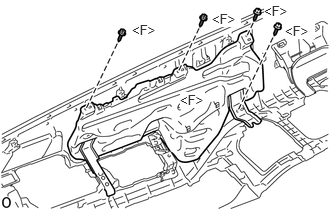
Remove the 4 screws <F> and inner No. 1 instrument panel reinforcement panel.
55085
2.REMOVE NO. 2 HEATER TO REGISTER DUCT SUB-ASSEMBLY (w/ Heater)
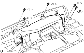
Remove the 5 screws <F> and No. 2 heater to register duct sub-assembly.
55084E
3.REMOVE NO. 1 HEATER TO REGISTER DUCT SUB-ASSEMBLY (w/ Heater)
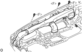
Remove the 4 screws <F> and No. 1 heater to register duct sub-assembly.
55950G
4.REMOVE DEFROSTER NOZZLE ASSEMBLY
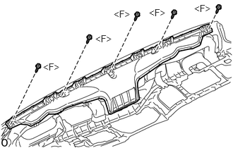
Remove the 5 screws <F> and defroster nozzle assembly.
55771
5.REMOVE UPPER INSTRUMENT PANEL BRACKET (w/o Passenger Side Airbag)
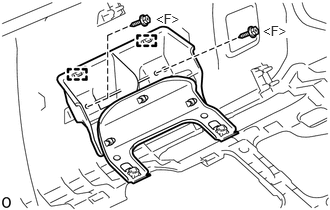
Remove the 2 screws <F>.
Detach the 2 guides and remove the upper instrument panel bracket.
86101
6.REMOVE ANTENNA CORD SUB-ASSEMBLY (w/ Antenna)
for LHD:
Click hereAudio / Visual / Telematics>AUDIO / VIDEO>RADIO ANTENNA CORD>REMOVAL
for RHD:
Click hereAudio / Visual / Telematics>AUDIO / VIDEO>RADIO ANTENNA CORD>REMOVAL
55366A
7.REMOVE NO. 1 RADIO MOUNTING BRACKET
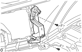
Remove the 2 screws <F> and No. 1 radio mounting bracket.
55548
8.REMOVE FUEL LID OPENER OPENING COVER (for LHD, w/o Fuel Lid Opener)
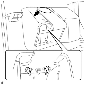
Remove the clip.
Detach the 2 claws and remove the fuel lid opener opening cover.
55617
9.REMOVE DEFOGGER KNOB HOLE COVER (for LHD, w/o Manual Idle Up)
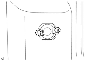
Detach the 2 claws and remove the defogger knob hole cover.
55539
10.REMOVE SPARE SWITCH HOLE COVER
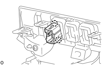
Detach the 2 claws and remove the spare switch hole cover.
- HINT:
-
Use the same procedure for all spare switch hole cover.
55447C
11.REMOVE NO. 2 SWITCH HOLE BASE
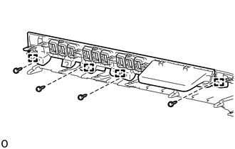
Remove the 4 screws.
Detach the 4 guides and remove the No. 2 switch hole base.
55660
12.REMOVE NO. 2 INSTRUMENT PANEL REGISTER ASSEMBLY (w/ Heater)
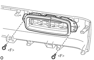
Remove the 2 screws <F> and No. 2 instrument panel register assembly.
- HINT:
-
Use the same procedure for all No. 2 instrument panel register assemblies.
55528D
13.REMOVE NO. 3 INSTRUMENT PANEL REGISTER OPENING COVER (w/o Heater)
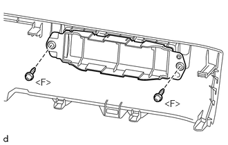
Remove the 2 screws <F> and No. 3 instrument panel register opening cover.
- HINT:
-
Use the same procedure for all No. 3 instrument panel register opening covers.
55650
14.REMOVE NO. 1 INSTRUMENT PANEL REGISTER ASSEMBLY (w/ Heater)
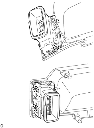
Detach the 4 clews and remove the No. 1 instrument panel register assembly.
55526A
15.REMOVE NO. 1 INSTRUMENT PANEL REGISTER OPENING COVER (w/o Heater)
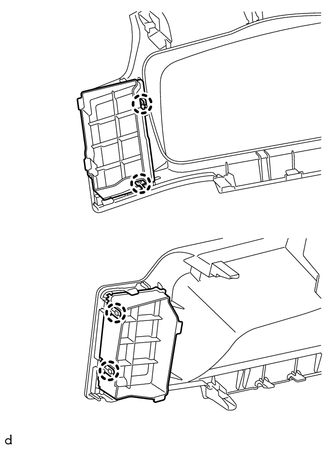
Detach the 4 crews and remove the No. 1 instrument panel register opening cover.
55524
16.REMOVE SWITCH BACE HOLE COVER (w/o Door Control Switch)
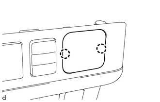
Detach the 2 claws and remove the switch base hole cover.
55474C
17.REMOVE NO. 1 INSTRUMENT CLUSTER FINISH PANEL GARNISH
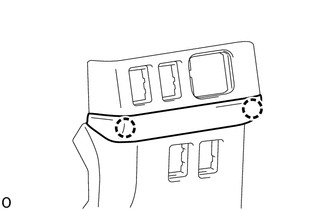
Detach the 2 claws and remove the No. 1 instrument cluster finish panel garnish.
55548A
18.REMOVE INSTRUMENT PANEL HOLE COVER (for RHD)
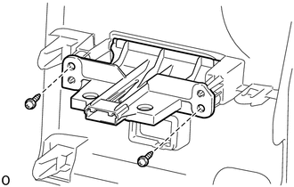
Remove the 2 screws and instrument panel hole cover.
55620
19.REMOVE INSTRUMENT PANEL CUP HOLDER ASSEMBLY
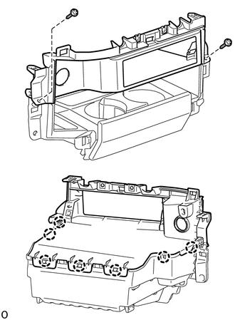
w/ Tachograph:
Remove the 2 screws.
Detach the 7 claws and remove the No. 2 instrument panel box.
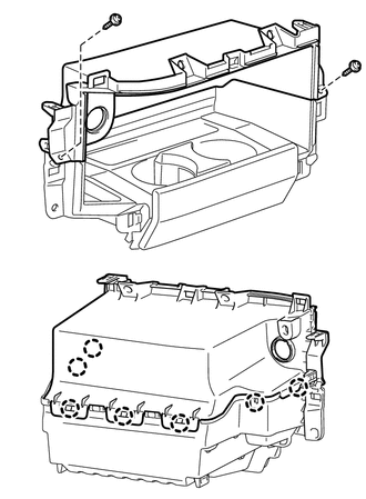
w/o Tachograph:
Remove the 2 screws.
Detach the 7 claws and remove the No. 2 instrument panel box.
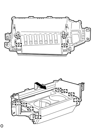
Detach the 2 claws and 2 guides on the backside of the No. 1 instrument panel box.
Detach the 8 guides in the direction indicated by the arrow in the illustration and remove the instrument panel cup holder assembly together with the No. 1 instrument panel cup holder rail and No. 2 instrument panel cup holder rail.
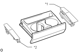
Remove the No. 1 instrument panel cup holder rail and No. 2 instrument panel cup holder rail from instrument panel cup holder assembly.
| *1 | No. 1 Instrument Panel Cup Holder Rail |
| *2 | No. 2 Instrument Panel Cup Holder Rail |
55633B
20.REMOVE INSTRUMENT PANEL CUP HOLDER SUPPORT
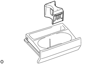
Remove the instrument panel cup holder support from instrument panel cup holder assembly.