INTERIOR PANEL INSTRUMENT PANEL SAFETY PAD REASSEMBLY
CAUTION / NOTICE / HINT
- HINT:
- ·
Use the same procedure for RHD and LHD vehicles.
·The procedure listed below is for RHD vehicles.
PROCEDURE

 55633B
1.INSTALL INSTRUMENT PANEL CUP HOLDER SUPPORT
Install the instrument panel cup holder support for instrument panel cup holder assembly.
55620
2.INSTALL INSTRUMENT PANEL CUP HOLDER ASSEMBLY
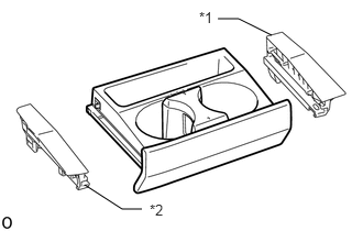
Install the No. 1 instrument panel cup holder rail and No. 2 instrument panel cup holder rail for instrument panel cup holder assembly.
| *1 | No. 1 Instrument Panel Cup Holder Rail |
| *2 | No. 2 Instrument Panel Cup Holder Rail |
Attach the 8 guides to install the No. 1 instrument panel cup holder rail and No. 2 instrument panel cup holder rail for No. 1 instrument panel box.
Attach the 2 claws and insert the 2 guides on the backside of the No. 1 instrument panel box.
w/ Tachograph:
Attach the 7 claws to install the No. 2 instrument panel box for No. 1 instrument panel box with the 2 screws.
w/o Tachograph:
Attach the 7 claws to install the No. 2 instrument panel box for No. 1 instrument panel box with the 2 screws.
55548A
3.INSTALL INSTRUMENT PANEL HOLE COVER (for RHD)
Install the instrument panel hole cover with 2 screws.
55474C
4.INSTALL NO. 1 INSTRUMENT CLUSTER FINISH PANEL GARNISH
Attach the 2 claws to install the No. 1 instrument cluster finish panel garnish.
55524
5.INSTALL SWITCH BACE HOLE COVER (w/o Door Control Switch)
Attach the 2 claws to install the switch base hole cover.
55650
6.INSTALL NO. 1 INSTRUMENT PANEL REGISTER ASSEMBLY (w/ Heater)
Attach the 4 claws to install the No. 1 instrument panel register assembly.
55526A
7.INSTALL NO. 1 INSTRUMENT PANEL REGISTER OPENING COVER (w/o Heater)
Attach the 4 claws to install the No. 1 instrument panel register opening cover.
55660
8.INSTALL NO. 2 INSTRUMENT PANEL REGISTER ASSEMBLY (w/ Heater)
Install the No. 2 instrument panel register assembly with the 2 screws.
- HINT:
-
Use the same procedure for all No. 2 instrument panel register assemblies.
55528D
9.INSTALL NO. 3 INSTRUMENT PANEL REGISTER OPENING COVER (w/o Heater)
Install the No. 3 instrument panel register opening cover with the 2 screws.
- HINT:
-
Use the same procedure for all No. 3 instrument panel register opening covers.
55539
10.INSTALL SPARE SWITCH HOLE COVER
Attach the 2 claws to install the spare switch hole cover.
55447C
11.INSTALL NO. 2 SWITCH HOLE BASE
Attach the 4 guides to install the No. 2 switch hole base with the 4 screws.
55617
12.INSTALL DEFOGGER KNOB HOLE COVER (for LHD, w/o Manual Idle Up)
Attach the 2 claws to install the defogger knob hole cover.
55548A
13.INSTALL INSTRUMENT PANEL HOLE COVER (for LHD, w/o Fuel Lid Opener)
Install the instrument panel hole cover with the clip and screw.
55366A
14.INSTALL NO. 1 RADIO MOUNTING BRACKET
Install the No. 1 radio mounting bracket with the 2 screws <F>.
86101
15.INSTALL ANTENNA CORD SUB-ASSEMBLY (w/ Antenna)
for LHD:
Click hereAudio / Visual / Telematics>AUDIO / VIDEO>RADIO ANTENNA CORD>INSTALLATION
for RHD:
Click hereAudio / Visual / Telematics>AUDIO / VIDEO>RADIO ANTENNA CORD>INSTALLATION
55771
16.INSTALL UPPER INSTRUMENT PANEL BRACKET (Passenger Side Airbag)
Attach the 2 guides to install the upper instrument panel bracket with the 2 screws <F>.
55950G
17.INSTALL DEFROSTER NOZZLE ASSEMBLY
Install the defroster nozzle assembly with the 5 screws <F>.
55084E
18.INSTALL NO. 1 HEATER TO REGISTER DUCT SUB-ASSEMBLY (w/ Heater)
Install the No. 1 heater to register duct sub-assembly with the 4 screws <F>.
55085
19.INSTALL NO. 2 HEATER TO REGISTER DUCT SUB-ASSEMBLY (w/ Heater)
Install the No. 2 heater to register duct sub-assembly with the 5 screws <F>.
55391A
20.INSTALL INNER NO. 1 INSTRUMENT PANEL REINFORCEMENT PANEL
Install the inner No. 1 instrument panel reinforcement panel with the 4 screws <F>.