BRAKE CONTROL / DYNAMIC CONTROL SYSTEMS ANTI-LOCK BRAKE SYSTEM(w/o Brake pedal Load Sensing Switch) TEST MODE PROCEDURE
SENSOR SIGNAL CHECK (TEST MODE) (When Using SST Check Wire)
Procedures for test mode:
Turn the ignition switch off.
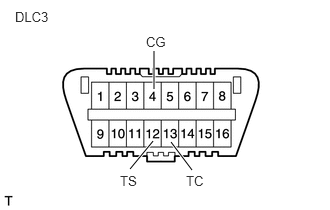
Using SST, connect terminals TS and CG of DLC3.
- SST
- 09843-18040
Turn the ignition switch to ON.
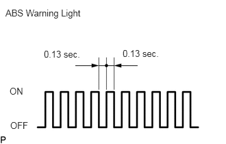
Check that the ABS warning light blinks.
- HINT:
- ·
If the ABS warning light does not blink, inspect the ABS warning light circuit (Click hereBrake>BRAKE CONTROL / DYNAMIC CONTROL SYSTEMS>ANTI-LOCK BRAKE SYSTEM (w/o Brake pedal Load Sensing Switch)>ABS Warning Light does not Come ON).
·If the ABS warning light remains ON, start and stop the engine and turn ON the ignition switch.
Master cylinder pressure sensor check:
After releasing the brake pedal for 1 second or more depress it by a force of 186 N (19 kgf, 42 lbf) or more.
Check that the ABS warning light is lit.
Depress the brake pedal for 1 second with the ABS warning light lit and release it.
Check that the blinking pattern of the ABS warning light is back to that in the test mode.
- HINT:
- ·
Do not depress a brake pedal several times.
·If the ABS warning light is not lit although depressing force is sufficient enough, the master cylinder pressure sensor may 6 defective.
Vacuum sensor check:
Depress the brake pedal several times.
Check that the ABS warning light is lit.
- HINT:
- ·
If the ABS warning light is not lit after depressing a brake pedal continuously, the vacuum sensor may be defective.
·When a parking brake is released, vacuum warning buzzer may sound.
Speed sensor check:
Start the engine.
Check that the ABS warning light blinks.
Drive vehicle straight forward. When driving the vehicle with the speed faster than 90 km/h (56 mph) for several seconds, check that the ABS warning light comes off.
- HINT:
-
There is a case that the sensor check is not completed if the vehicle has its rear wheels spun or its steering wheel steered during this check.
Stop the vehicle.
Read the DTC:
Using SST, connect terminals TC and CG of DLC3.
- SST
- 09843-18040
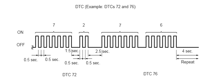
Read the number of blinks of the ABS warning light.
- HINT:
- ·
As an example, the blinking patterns for DTCs 72 and 76 are shown below.
·If every sensor is normal, a normal code is output (A cycle of 0.25 seconds. ON and 0.25 seconds. OFF is repeated).
·If 2 or more malfunctions are indicated at the same time, the lowest numbered code will be displayed 1st.
After the check, disconnect SST from terminals 13 (TC) and 4 (CG) of the DLC3.
- SST
- 09843-18040
Turn the ignition switch off.
SENSOR SIGNAL CHECK (TEST MODE) (When Using GTS)
Turn the ignition switch off.
Connect the GTS to the DLC3.
Turn the ignition switch to ON.
Turn the GTS on.
Switch the skid control ECU to Test Mode using the GTS. Enter the following menus: Chassis / ABS/VSC/TRC / Utility / Signal Check.
Check that the ABS warning light blinks.
- HINT:
- ·
If the ABS warning light does not blink, inspect the ABS warning light circuit (Click hereBrake>BRAKE CONTROL / DYNAMIC CONTROL SYSTEMS>ANTI-LOCK BRAKE SYSTEM (w/o Brake pedal Load Sensing Switch)>ABS Warning Light does not Come ON).
·If the ABS warning light remains ON, start and stop the engine and turn ON the ignition switch.
Master cylinder pressure sensor check:
After releasing the brake pedal for 1 second or more depress it by a force of 186 N (19 kgf, 42 lbf) or more.
Check that the ABS warning light is lit.
Depress the brake pedal for 1 second with the ABS warning light lit and release it.
Check that the blinking pattern of the ABS warning light is back to that in the test mode.
- HINT:
- ·
Do not depress a brake pedal several times.
·If the ABS warning light is not lit although depressing force is sufficient enough, the master cylinder pressure sensor may 6 defective.
Vacuum sensor check:
Depress the brake pedal several times.
Check that the ABS warning light is lit.
- HINT:
- ·
If the ABS warning light is not lit after depressing a brake pedal continuously, the vacuum sensor may be defective.
·When a parking brake is released, vacuum warning buzzer may sound.
Speed sensor check:
Start the engine.
Check that the ABS warning light blinks.
Drive vehicle straight forward. When driving the vehicle with the speed faster than 90 km/h (56 mph) for several seconds, check that the ABS warning light comes off.
- HINT:
-
There is a case that the sensor check is not completed if the vehicle has its rear wheels spun or its steering wheel steered during this check.
Stop the vehicle.
Read the DTC by following the prompts on the GTS.
- HINT:
-
Please refer to the GTS operator's manual for further details.
| Code No. | Diagnosis | Trouble Area |
|---|---|---|
| C1271 / 71 | Low output voltage of right front speed sensor | ·
Front speed sensor RH ·
Sensor installation ·
Front skid control rotor ·
Front speed sensor RH circuit |
| C1272 / 72 | Low output voltage of left front speed sensor | ·
Front speed sensor LH ·
Sensor installation ·
Front skid control rotor ·
Front speed sensor LH circuit |
| C1273 / 73 | Low output voltage of right rear speed sensor | ·
Rear speed sensor RH ·
Sensor installation ·
Rear skid control rotor ·
Rear speed sensor RH circuit |
| C1274 / 74 | Low output voltage of left rear speed sensor | ·
Rear speed sensor LH ·
Sensor installation ·
Rear skid control rotor ·
Rear speed sensor LH circuit |
| C1275 / 75 | Abnormal change in output voltage of right front speed sensor | ·
Front skid control rotor ·
Front speed sensor RH |
| C1276 / 76 | Abnormal change in output voltage of left front speed sensor | ·
Front skid control rotor ·
Front speed sensor LH |
| C1277 / 77 | Abnormal change in output voltage of right rear speed sensor | ·
Rear skid control rotor ·
Rear speed sensor RH |
| C1278 / 78 | Abnormal change in output voltage of left rear speed sensor | ·
Rear skid control rotor ·
Rear speed sensor LH |
| C1281 / 81 | Abnormal change in output signal of master cylinder pressure sensor | ·
Master cylinder pressure sensor ·
Master cylinder pressure sensor circuit |
| C1285 / 85 | Abnormal change in output signal of vacuum sensor | ·
Vacuum sensor ·
Vacuum sensor circuit |