RM2850E
_54
Brake
_073264
BRAKE CONTROL / DYNAMIC CONTROL SYSTEMS
_0356879
ANTI-LOCK BRAKE SYSTEM(w/o Brake pedal Load Sensing Switch)
U
BRAKE CONTROL / DYNAMIC CONTROL SYSTEMS ANTI-LOCK BRAKE SYSTEM(w/o Brake pedal Load Sensing Switch) TERMINALS OF ECU
TERMINALS OF ECU
1.177,0.771 1.573,1.01
0.396,0.24
3.031,0.771 3.427,1.01
0.396,0.24
4.281,0.771 4.677,1.01
0.396,0.24
5.781,0.771 6.177,1.01
0.396,0.24
4.281,0.448 4.677,0.688
0.396,0.24
1.25,0.802 1.74,1
0.49,0.198
10
false
A47
3.104,0.802 3.625,1
0.521,0.198
10
false
A48
4.354,0.813 4.698,1
0.344,0.188
10
false
A49
5.854,0.813 6.406,1.042
0.552,0.229
10
false
A50
0.135,0.125 0.406,0.385
0.271,0.26
10
false
*a
4.354,0.49 4.698,0.677
0.344,0.188
10
false
B53
4.771,0.49 5.042,0.75
0.271,0.26
10
false
*B
4.781,0.813 5.052,1.073
0.271,0.26
10
false
*A
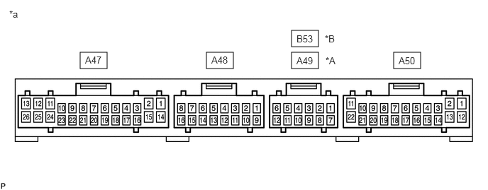
| *A | for LHD | *B | for RHD |
| *a | Component with harness connected
(Skid Control ECU) |
- | - |
- HINT:
-
The standard voltage or resistance between each pair of the skid control ECU terminals is shown in the table below. The appropriate conditions for checking each pair of terminals are also indicated. The result of checks should be compared with the standard voltage or resistance for that pair of terminals, displayed in the Specified Condition column. The illustration above can be used as a reference to identify the skid control ECU terminal locations.
| Terminal No. (Symbol) | Wiring Color | Terminal Description | Condition | Specified Condition |
|---|---|---|---|---|
| A47-1 (SRLH) - Body ground | G - Body ground | Rear holding solenoid LH output | Ignition switch ON, ABS warning light OFF | 11 to 14 V |
| A47-2 (SRLR) - Body ground | SB - Body ground | Rear reduction solenoid LH output | Ignition switch ON, ABS warning light OFF | 11 to 14 V |
| A47-3 (MT) - Body ground | LG - Body ground | Motor relay test input | Ignition switch ON (Motor relay is OFF) | Below 2.0 V |
| A47-5 (RSS) - Body ground | BR - Body ground | Rear wheel speed sensor shielded ground | Always | Below 1 Ω |
| A47-7 (SRRH) - Body ground | P - Body ground | Rear holding solenoid RH output | Ignition switch ON, ABS warning light OFF | 11 to 14 V |
| A47-8 (SFLH) - Body ground | W - Body ground | Front holding solenoid LH output | Ignition switch ON, ABS warning light OFF | 11 to 14 V |
| A47-9 (SMCF) - Body ground | GR - Body ground | Front master cylinder cut solenoid output | Ignition switch ON, ABS warning light OFF | 11 to 14 V |
| A47-10 (SMCR) - Body ground | R - Body ground | Rear master cylinder cut solenoid output | Ignition switch ON, ABS warning light OFF | 11 to 14 V |
| A47-11 (AST) - Body ground | B - Body ground | Solenoid relay test input | Ignition switch ON, ABS warning light OFF | 11 to 14 V |
| A47-12 (SRCR) - Body ground | GR - Body ground | Rear reservoir cut solenoid output | Ignition switch ON, ABS warning light OFF | 11 to 14 V |
| A47-13 (SFLR) - Body ground | P - Body ground | Front reduction solenoid LH output | Ignition switch ON, ABS warning light OFF | 11 to 14 V |
| A47-14 (SFRH) - Body ground | V - Body ground | Front holding solenoid RH output | Ignition switch ON, ABS warning light OFF | 11 to 14 V |
| A47-15 (SFRR) - Body ground | L - Body ground | Front reduction solenoid RH output | Ignition switch ON, ABS warning light OFF | 11 to 14 V |
| A47-16 (RR-) - Body ground | BR - Body ground | Rear wheel speed sensor RH (-) input | Ignition switch OFF | Below 1 Ω |
| A47-17 (RR+) - Body ground | Y - Body ground | Rear wheel speed sensor RH (+) input | Ignition switch ON, slowly turn right rear wheel | Pulse generation |
| A47-18 (RL-) - Body ground | B - Body ground | Rear wheel speed sensor LH (-) input | Ignition switch OFF | Below 1 Ω |
| A47-19 (RL+) - Body ground | W - Body ground | Rear wheel speed sensor LH (+) input | Ignition switch ON, slowly turn left rear wheel | Pulse generation |
| A47-25 (SRCF) - Body ground | V - Body ground | Front reservoir cut solenoid output | Ignition switch ON, ABS warning light OFF | 11 to 14 V |
| A47-26 (SRRR) - Body ground | LG - Body ground | Rear reduction solenoid RH output | Ignition switch ON, ABS warning light OFF | 11 to 14 V |
| A48-3 (VCM) - Body ground | B - Body ground | Master cylinder pressure sensor power supply output | Ignition switch ON, ABS warning light OFF | 4.75 to 5.25 V |
| A48-4 (E2) - Body ground | R - Body ground | Master cylinder pressure sensor ground | Always | Below 1 Ω |
| A48-5 (VCP) - Body ground | B - Body ground | Vacuum sensor 1 power supply output | Ignition switch ON, ABS warning light OFF | 4.75 to 5.25 V |
| A48-6 (PIM) - Body ground | W - Body ground | Vacuum sensor 1 input | Engine idling | 0.5 to 4 V |
| A48-7 (E3) - Body ground | R - Body ground | Vacuum sensor 1 ground | Always | Below 1 Ω |
| A48-8 (VSS) - Body ground | Shielded - Body ground | Vacuum sensor 1 shielded ground | Always | Below 1 Ω |
| A48-11 (PMC) - Body ground | W - Body ground | Master cylinder pressure sensor input | Ignition switch ON, stop light switch released | 0.3 to 0.7 V |
| A48-12 (PSS) - Body ground | Shielded - Body ground | Master cylinder pressure sensor shielded ground | Always | Below 1 Ω |
| A48-13 (VCP2) - Body ground | B - Body ground | Vacuum sensor 2 power supply output | Ignition switch ON, ABS warning light OFF | 4.75 to 5.25 V |
| A48-14 (PIM2) - Body ground | W - Body ground | Vacuum sensor 2 input | Engine idling | 0.5 to 4 V |
| A48-15 (E4) - Body ground | R - Body ground | Vacuum sensor 2 ground | Always | Below 1 Ω |
| A48-16 (VSS2) - Body ground | Shielded - Body ground | Vacuum sensor 2 shielded ground | Always | Below 1 Ω |
| A49-2 (TC) - Body ground*3
A53-2 (TC) - Body ground*4 |
P1*1, L*2 - Body ground | Diagnosis activation input | Ignition switch ON, terminals TC and CG of DLC3 connected → disconnected | Below 1 V → 11 to 14 V |
| A49-3 (FR-) - Body ground*1
B53-3 (FR-) - Body ground*2 |
B - Body ground | Front wheel speed sensor RH (-) input | Ignition switch OFF | Below 1 Ω |
| A49-4 (FR+) - Body ground*1
B53-4 (FR+) - Body ground*2 |
W - Body ground | Front wheel speed sensor RH (+) input | Ignition switch ON, slowly turn right front wheel | Pulse generation |
| A49-5 (FL-) - Body ground*1
B53-5 (FL-) - Body ground*2 |
G - Body ground | Front wheel speed sensor LH (-) input | Ignition switch OFF | Below 1 Ω |
| A49-6 (FL+) - Body ground*1
B53-6 (FL+) - Body ground*2 |
R - Body ground | Front wheel speed sensor LH (+) input | Ignition switch ON, slowly turn right front wheel | Pulse generation |
| A49-8 (TS) - Body ground*3
B53-8 (TS) - Body ground*4 |
GR - Body ground*2
B - Body ground*1 |
Sensor check activation input | Ignition switch ON, terminals TS and CG of DLC3 connected → disconnected | Below 1 V → 11 to 14 V |
| A49-9 (FSS) - Body ground*1
B53-9 (FSS) - Body ground*2 |
BR - Body ground | Front wheel speed sensor shielded ground | Always | Below 1 Ω |
| A50-2 (GND3) - Body ground | W-B - Body ground | Skid control ECU ground 3 | Always | Below 1 Ω |
| A50-5 (BRL) - Body ground | GR - Body ground | BRAKE warning light output | Ignition switch ON, parking brake switch ON | 4 to 11 V |
| Ignition switch ON, parking brake switch OFF | Below 2.0 V | |||
| A50-6 (WA) - Body ground | R - Body ground | ABS warning light output | Ignition switch ON, ABS warning light ON | 4 to 11 V |
| Ignition switch ON, ABS warning light OFF | Below 2.0 V | |||
| A50-7 (SR) - Body ground | P - Body ground | Solenoid relay output | Ignition switch ON, ABS warning light OFF | Below 2.0 V |
| A50-8 (MR) - Body ground | V - Body ground | Motor relay output | Ignition switch ON, ABS motor stops | 11 to 14 V |
| A50-9 (STP) - Body ground | G - Body ground | Stop light switch input | Brake pedal depressed | 8 to 14 V |
| Brake pedal released | Below 2.0 V | |||
| A50-10 (IG1) - Body ground | B - Body ground | IG1 power supply | Ignition switch ON | 11 to 14 V |
| A50-11 (GND1) - Body ground | W-B - Body ground | Skid control ECU ground 1 | Always | Below 1 Ω |
| A50-13 (GND4) - Body ground | W-B - Body ground | Skid control ECU ground 4 | Always | Below 1 Ω |
| A48-17 (D/G) - Body ground | R - Body ground | Diagnosis tester communication line | Using GTS | Communication possible |
| A50-18 (EXO) - Body ground*2 | Y - Body ground | Exhaust brake out request output | Ignition switch ON, ABS warning light OFF | 9 to 14 V |
| A50-19 (PKB) - Body ground | SB - Body ground | Parking brake switch input | Ignition switch ON, parking brake switch ON | Below 2.0 V |
| Ignition switch ON, parking brake switch OFF | 11 to 14 V | |||
| A50-21 (R+) - Body ground | L - Body ground | Relay power supply | Ignition switch ON, ABS warning light OFF | 11 to 14 V |
| A50-22 (GND2) - Body ground | W-B - Body ground | Skid control ECU ground 2 | Always | Below 1 Ω |
*1: except N04C-UH
*2: for N04C-UH
*3: for LHD
*4: for RHD