RM2850E
_54
Brake
_073264
BRAKE CONTROL / DYNAMIC CONTROL SYSTEMS
_0356879
ANTI-LOCK BRAKE SYSTEM(w/o Brake pedal Load Sensing Switch)
G
BRAKE CONTROL / DYNAMIC CONTROL SYSTEMS ANTI-LOCK BRAKE SYSTEM(w/o Brake pedal Load Sensing Switch) INSPECTION
PROCEDURE

 89421E
1. VACUUM SENSOR CHECK
a.
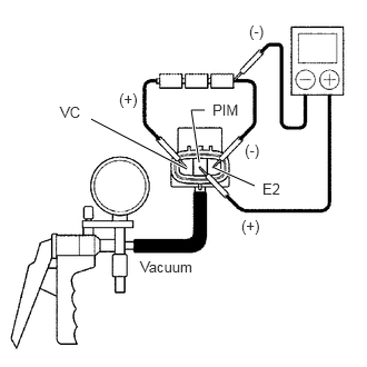
2.01,1.573 2.385,1.74
true
0.854,1.115 1.75,1.583
true
1.917,1.031 1.792,1.031
1.792,1.031 1.865,1.521
true
0.563,0.969 0.875,1.167
0.313,0.198
10
false
VC
1.115,0.844 1.427,1.042
0.313,0.198
10
false
(+)
2.333,0.208 2.646,0.406
0.313,0.198
10
false
(-)
1.99,0.948 2.344,1.146
0.354,0.198
10
false
PIM
2.292,1.323 2.604,1.521
0.313,0.198
10
false
(-)
2.458,1.688 2.771,1.885
0.313,0.198
10
false
E2
2.26,2.031 2.573,2.229
0.313,0.198
10
false
(+)
1.313,2.417 1.896,2.656
0.583,0.24
10
false
Vacuum
Connect 3 dry batteries of 1.5 V in series.
b.
Connect VC terminal to the batteries' positive (+) terminal, and E2 terminal to the batteries' negative (-) terminal, apply about 4.5 V between VC and E2 terminals.
- NOTICE:
-
Do not apply voltage of 6 V or more to terminals VC and E2.
c.
Connect a voltmeter to terminals PIM and E2 of the ECU, and measure the output voltage under ambient atmospheric pressure. (*)
d.
Apply vacuum to the vacuum sensor in segments from 13.3 kPa (100 mmHg, 3.94 in.Hg) to 66.7 kPa (500 mmHg, 19.69 in.Hg).
e.
Measure the voltage drop from step (*) above for each segment.
| Applied Vacuum kPa (mmHg, in.Hg) | 13.3
(100, 3.94) |
26.7
(200, 7.87) |
40.0
(300,11.81) |
53.5
(400,15.75) |
66.7
(500,19.69) |
| Voltagedrop V | 0.26 to 0.46 | 0.62 to 0.82 | 0.98 to 1.18 | 1.34 to 1.54 | 1.7 to 1.9 |