1BZ-FPE ENGINE CONTROL ELECTRONIC CONTROLLED CARBURETOR SYSTEM TERMINALS OF ECM
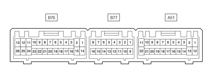
- HINT:
-
Each ECM terminal's standard normal voltage is shown in the table below.
-
In the table, first check the information under "Condition". Look under "Terminal No. (Symbols)" for the terminals to be inspected. The standard voltage between the terminals is shown under "Specified Condition".
-
Use the illustration above as a reference for the ECM terminals.
| Terminal No. (Symbols) | Wiring Color | Terminal Description | Condition | Specified Condition |
|---|---|---|---|---|
| A51-1 (BATT) - B76-24 (E1) | GR - BR | Battery (for measuring battery voltage and for ECM memory) | Always | 9 to 14 V |
| A51-13 (IGSW) - B76-24 (E1) | B - BR | Ignition switch | Ignition switch ON | 9 to 14 V |
| A51-2 (MREL) - B76-24 (E1) | B - BR | ENG STOP/P LOCK NO. 2 relay | Ignition switch ON | 9 to 14 V |
| A51-12 (+B) - B76-24 (E1) | B - BR | Power source of ECM | Ignition switch ON | 9 to 14 V |
| B77-11 (VC) - B77-9 (E2) | V - W-B | Power source of sensor (specific voltage) | Ignition switch ON | 4.5 to 5.5 V |
| B77-2 (PIM) - B77-9 (E2) | R - W-B | Vacuum sensor | Ignition switch ON | 3.3 to 3.9 V |
| Apply vacuum 67 kPa (503 mmHg, 19.79 in.Hg) | 1.3 to 1.9 V | |||
| B77-4 (THW) - B77-9 (E2) | BR - W-B | ECT sensor | Idling, engine coolant temp. 80°C (176°F) | 0.2 to 1.0 V |
| A51-11 (STA) - B76-24 (E1) | B - BR | Starter signal | Cranking | 6.0 V or more |
| B76-12 (#10) - B76-13 (E01) | L - W-B | Injector | Ignition switch ON | 9 to 14 V |
| Idling | Pulse generation (see waveform 1) | |||
| B76-25 (#20) - B76-13 (E01) | G - W-B | Injector | Ignition switch ON | 9 to 14 V |
| Idling | Pulse generation (see waveform 1) | |||
| B76-6 (IGT) - B76-24 (E1) | R - BR | Ignition coil(ignition signal) | Idling | Pulse generation (see waveform 2) |
| B76-3 (IGF) - B76-24 (E1) | B - BR | Ignition coil(ignition confirmation signal) | Ignition switch ON, disconnect igniter connector | 4.5 to 5.5 V |
| Idling | Pulse generation (see waveform 2) | |||
| B76-4 (NE) - B76-17 (NE-) | B - W | NE signal | Idle after engine warm-up | Pulse generation (see waveform 3) |
| A51-5 (LPGR) - B76-24 (E1) | V - BR | ENG MAIN/LPG relay | Ignition switch ON | 9 to 14 V |
| Idling | 0 to 3.0 V | |||
| B76-10 (FCM1) - B76-24 (E1) | V - BR | Air fuel ratio control motor | Ignition switch ON, disconnect B76 connector from ECM | 9 to 14 V |
| B76-23 (FCM2) - B76-24 (E1) | LG - BR | Air fuel ratio control motor | Ignition switch ON, disconnect B76 connector from ECM | 9 to 14 V |
| B76-9 (FCM3) - B76-24 (E1) | P - BR | Air fuel ratio control motor | Ignition switch ON, disconnect B76 connector from ECM | 9 to 14 V |
| B76-22 (FCM4) - B76-24 (E1) | L - BR | Air fuel ratio control motor | Ignition switch ON, disconnect B76 connector from ECM | 9 to 14 V |
| A51-22 (NSW) - B76-24 (E1) | B - BR | Shift position signal | Ignition switch ON, shift position in P or N | 0 to 3.0 V |
| A51-9 (SPD) - B76-24 (E1) | V - BR | Speed signal from combination meter | Ignition switch ON, rotate driving wheel slowly | Pulse generation (see waveform 4) |
| B77-15 (TE1) - B76-24 (E1) | L - BR | Check terminal of DLC1 | Ignition switch ON | 9 to 14 V |
| A51-3 (W) - B76-24 (E1) | R - BR | MIL | Idling | 9 to 14 V |
| Ignition switch ON | 0 to 3.0 V | |||
| A51-15 (FC) - B76-24 (E1) | R - BR | Fuel pump control | Ignition switch ON | 9 to 14 V |
| Idling | 0 to 3.0 V | |||
| A51-17 (ELS) - B76-24 (E1) | B - BR | Stop light switch | Stop light switch ON | 8 to 14 V |
| Stop light switch OFF | 0 to 1.5 V | |||
| A51-16 (ELS2) - B76-24 (E1) | G - BR | Electric load | Light control switch TAIL or HEAD | 8 to 14 V |
| Light control switch OFF | 0 to 1.5 V | |||
| B77-5 (THA) - B76-24 (E1) | W - BR | IAT sensor | Idling, intake air temp. 20°C (68°F) | 0.5 to 3.4 V |
| B77-6 (OX1A) - B76-24 (E1) | W - BR | Heated oxygen sensor (sensor 1) | Maintain engine speed at 2500 rpm for 2 minutes after warming up | Pulse generation (see waveform 5) |
| B77-13 (OX1B) - B76-24 (E1) | W - BR | Heated oxygen sensor (sensor 2) | Maintain engine speed at 2500 rpm for 2 minutes after warming up | Pulse generation (see waveform 6) |
| B77-8 (VF) - B76-24 (E1) | Y - BR | Idle adjust voltage | Maintain engine speed at 2500 rpm for 2 minutes after warming up | 1.8 to 3.2 V |
| B77-12 (IDL) - B76-24 (E1) | R - BR | Throttle position sensor | Ignition switch ON, throttle valve fully closed | 0 to 3.0 V |
| Ignition switch ON, throttle valve fully opened | 4.5 to 5.5 V | |||
| B77-10 (VTA) - B76-24 (E1) | R - BR | Throttle position sensor | Ignition switch ON, throttle valve fully closed | 0.3 to 1.0 V |
| Ignition switch ON, throttle valve fully opened | 3.2 to 4.9 V | |||
| B76-11 (HT1A) - B76-24 (E1) | R - BR | Heated oxygen sensor heater (sensor 1) | Idling | 0 to 3.0 V |
| Ignition switch ON | 9 to 14 V | |||
| B76-1 (HT1B) - B76-24 (E1) | L - BR | Heated oxygen sensor heater (sensor 2) | Idling | 0 to 3.0 V |
| Ignition switch ON | 9 to 14 V | |||
| B76-8 (ISC) - B76-24 (E1) | W - BR | Idle speed control valve | Ignition switch ON, disconnect B76 connector from ECM | 9 to 14 V |
| B76-21 (ISC2) - B76-24 (E1) | Y - BR | Idle speed control valve | Ignition switch ON, disconnect B76 connector from ECM | 9 to 14 V |
| B76-7 (ISC3) - B76-24 (E1) | G - BR | Idle speed control valve | Ignition switch ON, disconnect B76 connector from ECM | 9 to 14 V |
| B76-20 (ISC4) - B76-24 (E1) | P - BR | Idle speed control valve | Ignition switch ON, disconnect B76 connector from ECM | 9 to 14 V |
| B77-16 (PS) - B76-13 (E01) | R - W-B | Power steering oil pressure switch | Ignition switch ON, facing straight ahead steering wheel | 4.5 to 5.5 V |
| Ignition switch ON, turning steering wheel | 9 to 14 V |
Waveform 1
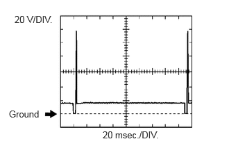
| Item | Content |
|---|---|
| Terminal No. (Symbols) | B76-12 (#10), B76-25 (#20) - B76-13 (E01) |
| Tool Setting | 20 V/DIV., 20 msec./DIV. |
| Condition | Idling |
- HINT:
-
The wavelength becomes shorter as engine speed increases.
Waveform 2
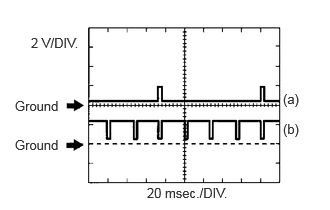
| Item | Content |
|---|---|
| Terminal No. (Symbols) | (a) B76-6 (IGT) - B76-24 (E1) |
| Tool Setting | 2 V/DIV., 20 msec./DIV. |
| Condition | Idling |
| Item | Content |
|---|---|
| Terminal No. (Symbols) | (b) B76-3 (IGF) - B76-24 (E1) |
| Tool Setting | 2 V/DIV., 20 msec./DIV. |
| Condition | Idling |
- HINT:
-
The wavelength becomes shorter as engine speed increases.
Waveform 3
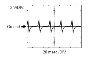
| Item | Content |
|---|---|
| Terminal No. (Symbols) | (a) B76-4 (NE) - B76-17 (NE-) |
| Tool Setting | 2 V/DIV., 20 msec./DIV. |
| Condition | Idle after engine warm-up |
- HINT:
-
The wavelength becomes shorter as engine speed increases.
Waveform 4
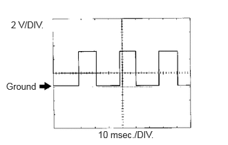
| Item | Content |
|---|---|
| Terminal No. (Symbols) | A51-9 (SPD) - B76-24 (E1) |
| Tool Setting | 2 V/DIV., 10 msec./DIV. |
| Condition | Ignition switch ON, rotate driving wheel slowly |
- HINT:
-
The duty ratio varies depending on the throttle opening operation.
Waveform 5
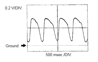
| Item | Content |
|---|---|
| Terminal No. (Symbols) | B77-6 (OX1A) - B76-24 (E1) |
| Tool Setting | 0.2 V/DIV., 500 msec./DIV. |
| Condition | Maintain engine speed at 2500 rpm for 2 minutes after warming up |
- HINT:
-
In the Data List, item O2S B1 S1 shows the ECM input values from the HO2 sensor (sensor 1).
Waveform 6
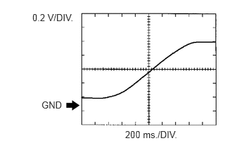
| Item | Content |
|---|---|
| Terminal No. (Symbols) | B77-13 (OX1B) - B76-24 (E1) |
| Tool Setting | 0.2 V/DIV., 200 msec./DIV. |
| Condition | Maintain engine speed at 2500 rpm for 2 minutes after warming up |
- HINT:
-
In the Data List, item O2S B1 S2 shows the ECM input values from the rear HO2 sensor (sensor 2).