1BZ-FPE ENGINE CONTROL ELECTRONIC CONTROLLED CARBURETOR SYSTEM DATA LIST / ACTIVE TEST
READ DATA LIST
- HINT:
-
Using an intelligent tester's Data List allows switch, sensor, actuator, and other item values to be read without removing any parts. Reading the Data List early in troubleshooting is one way to save time.
- NOTICE:
-
In the table below, the values listed under "Normal Condition" are reference values. Do not depend solely on these reference values when deciding whether a part is faulty or not.
Warm up the engine.
Turn the ignition switch to OFF.
Connect an intelligent tester to the DLC3.
Turn the Ignition switch to ON.
Turn the intelligent tester ON.
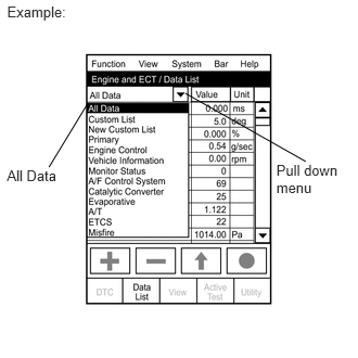
Select the following menu items: Powertrain / Engine and ECT / Data List.
- HINT:
-
To display the entire Data List, press the pull down menu button next to Primary. Then select All Data.
Read the Data List on the tester's screen.
| Tester Display | Measurement Item/Range | Normal Condition | Diagnostic Note |
|---|---|---|---|
| Injector | Injection period of No. 1 cylinder/
Min.: 0 ms, Max.: 32.6 ms |
Idling: 1 to 3 ms | - |
| IGN Advance | Ignition timing advance for No. 1 cylinder/
Min.: -64°, Max.: 63.5° |
Idling: BTDC 0 to 20° | - |
| CALC Load | ECM calculated load/
Min.: 0%, Max.: 99.96% |
·
Idling: 10 to 30% ·
Running without load (2,500 rpm): 10 to 40% |
- |
| Engine SPD | Engine speed/
Min.: 0 rpm, Max.: 16,383.75 rpm |
Idling:
750 to 850 rpm |
- |
| Coolant Temp | Engine coolant temperature/
Min.: -40°C (-40°F) Max.: 215°C (419°F) |
After warming up engine:
80 to 95°C (176 to 203°F) |
·
If value is -40°C (-40°F): sensor circuit is open ·
If value is 140°C (284°F): sensor circuit is shorted |
| Intake Air | Intake air temperature/
Min.: -40°C (-40°F) Max.: 215°C (419°F) |
Equivalent to ambient air temperature | ·
If value is -40°C (-40°F): sensor circuit is open ·
If value is 140°C (284°F): sensor circuit is shorted |
| Throttle POS | Absolute throttle position sensor/
Min.: 0%, Max.: 99.96% |
·
Throttle fully closed: 10 to 22% ·
Throttle fully open: 66 to 98% |
Read value with intrusive operation (active test) |
| Vehicle SPD | Vehicle speed/
Min.: 0 km/h, Max.: 255 km/h |
Actual vehicle speed | Speed indicated on speedometer |
| O2S B1 S2 | Heated oxygen sensor output voltage for bank 1 sensor 2/
Min.: 0 V, Max.: 1.275 V |
Driving 70 km/h (44 mph): 0.1 to 0.9 V | Performing Control the Injection Volume or Control the Injection Volume for A/F Sensor function of Active Test enables technician to check output voltage of sensor |
| AFS B1 S1 | Heated oxygen sensor output voltage for bank 1 sensor 1/
Min.: 0 V, Max.: 5 V |
Idling: 2.8 to 3.8 V | Performing Control the Injection Volume or Control the Injection Volume for A/F Sensor function of Active Test enables technician to check output voltage of sensor |
| Short FT #1 | Short-term fuel trim of bank 1/
Min.: -100%, Max.: 99.15% |
-20 to 20% | Short-term fuel compensation used to maintain air-fuel ratio at stoichiometric air-fuel ratio |
| Long FT #1 | Long-term fuel term of bank 1/
Min.: -100%, Max.: 99.15% |
-20 to 20% | Overall fuel compensation carried out in long-term to compensate continual deviation of short-term fuel trim from central value |
| AF FT B1 S1 | Short-term fuel trim associated with bank 1 sensor 1/
Min.: -100%, Max.: 99.15% |
·
Value less than 1 (0.000 to 0.999) = Rich ·
Stoichiometric air-fuel ratio = 1 ·
Value greater than 1 (1.001 to 1.999) = Lean |
- |
| FUEL SYS #1 | Fuel system status (Bank 1) /
OL, CL, OL DRIVE, OL FAULT or CL FAULT |
Idling after warming up: CL | ·
OL (Open Loop): Has not yet satisfied conditions to go closed loop ·
CL (Closed Loop): Using heated oxygen sensor(s) as feedback for fuel control ·
OL DRIVE: Open loop due to driving conditions (fuel enrichment) ·
OL FAULT: Open loop due to detected system fault ·
CL FAULT: Closed loop but heated oxygen sensor which is used for fuel control is malfunctioning |
| MIL Status | MIL status/ ON or OFF | MIL ON: ON | - |
| IGNITION | Ignition counter/
Min.: 0, Max.: 4000 |
- | - |
| Cylinder #1 Misfire Count | Counting of nisfire for cylinder #1/
Min.: 0, Max.: 510 |
- | - |
| Cylinder #2 Misfire Count | Counting of nisfire for cylinder #2/
Min.: 0, Max.: 510 |
- | - |
| Cylinder #3 Misfire Count | Counting of nisfire for cylinder #3/
Min.: 0, Max.: 510 |
- | - |
| Cylinder #4 Misfire Count | Counting of nisfire for cylinder #4/
Min.: 0, Max.: 510 |
- | - |
| MISFIRE RPM | Average engine RPM when misfire detected/
Min.: 0, Max.: 6375 rpm |
- | - |
| MISFIRE LOAD | Average engine load when misfire detected/
Min.: 0, Max.: 3.97 g/rev |
- | - |
| #Codes | #Codes/
Min.: 0, Max.: 255 |
- | Number of detected DTC |
| Distance after MIL ON | Distance traveled while MIL is activated/
Min.: 0 km, Max.: 65,535 km |
Distance after DTC is detected | - |
- HINT:
-
*: If no conditions are specifically stated for "Idling", the A/C switch is OFF and all accessory switches are OFF.
PERFORM ACTIVE TEST
- HINT:
-
Performing the intelligent tester's Active Test allows relay, VSV, actuator and other items to be operated without removing any parts. Performing the Active Test early in troubleshooting is one way to save time.
-
The Data List can be displayed during the Active Test.
Warm up the engine.
Turn the ignition switch to OFF.
Connect the intelligent tester to the DLC3.
Turn the ignition switch to ON.
Turn the intelligent tester ON.
Select the following menu items: Powertrain / Engine and ECT / Active Test.
According to the display on the tester, perform the Active Test.
| Tester Display | Test Part | Control Range | Diagnostic Note |
|---|---|---|---|
| Injector volume | Control injection volume
(Engine speed: 3,000 rpm or less) |
Min.: -12.5%, Max.: 24.8% | ·
All injectors are tested at once ·
Injection volume is gradually changed between -12.5% and 24.8% |
| A/F control | Change injection volume
(Engine speed: 3,000 rpm or less) |
Decreases by -12.5% or increases by 25% | Following A/F Control procedure enables technician to check and graph output voltages of the heated oxygen sensor
To display graph indication, select following menu items: View / Line graph 1 or Line graph 2 |