N04C-UH EXHAUST EXHAUST PIPE INSTALLATION
PROCEDURE

 18450
1.INSTALL MONOLITHIC CONVERTER ASSEMBLY
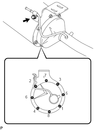
Install a new gasket onto the monolithic converter.
Provisionally install the center exhaust pipe assembly and the support bracket onto the monolithic converter with the 8 nuts.
Tighten the 8 nuts in the sequence shown in the illustration.Remove the gasket.
- Torque:
- 35 N*m (357 kgf*cm, 26 ft.*lbf)
Install a new pipe spacer and the pipe clamp with the bolt and nut.
- Torque:
- 18 N*m (184 kgf*cm, 13 ft.*lbf)
17460
2.INSTALL CATALYTIC WITH PIPE CONVERTER ASSEMBLY
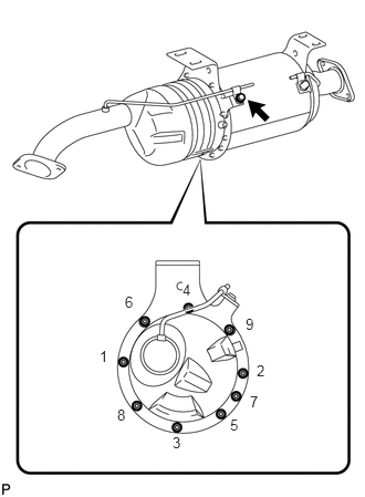
Install a new gasket onto the monolithic converter.
Provisionally install the center exhaust pipe assembly and the support bracket onto the monolithic converter with the 8 nuts.
Tighten the 9 nuts in the sequence shown in theillustration.
- Torque:
- 35 N*m (357 kgf*cm, 26 ft.*lbf)
Install a new pipe spacer and the pipe clamp with the bolt and nut.
- Torque:
- 18 N*m (184 kgf*cm, 13 ft.*lbf)
17410
3.INSTALL FRONT EXHAUST PIPE ASSEMBLY
Install a new gasket.
Temporarily install the front exhaust pipe with 3 new nuts.
Temporarily install a new clamp bolt.
Tighten the bolt.
- Torque:
28 N*m (282 kgf*cm, 20 ft.*lbf)
Tighten the 3 nuts.
- Torque:
62 N*m (632 kgf*cm, 46 ft.*lbf)
17402
4.INSTALL FRONT NO. 2 EXHAUST PIPE SUB-ASSEMBLY
Install the 2 new gaskets.
Install the exhaust retarder and the front No. 2 exhaust pipe with the 4 bolts.
- Torque:
27 N*m (275 kgf*cm, 20 ft.*lbf)
44763G
5.CONNECT SOLENOID TO RETARDER HOSE
Connect the solenoid to retarder hose.
17420K
6.INSTALL NO. 2 CENTER EXHAUST PIPE ASSEMBLY
Inspect the compression spring.
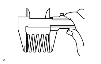
Using a vernier caliper, measure the free length of the compression spring.
- Minimum length:
38.5 mm (1.516 in.)
If the free length is less than the minimum, replace the compression spring.
Install a new gasket.
- NOTICE:
- ·
Install the gasket in the correct direction.
·Do not damage the outer surface of the gasket.
·Do not reuse the removed gasket.
·Do not push in the gasket with the No. 2 center exhaust pipe assembly when connecting it.
Install the No. 2 center exhaust pipe assembly with 4 new nuts.
- Torque:
19 N*m (194 kgf*cm, 14 ft.*lbf)
Tighten the 2 compression springs and the 2 bolts.
- Torque:
43 N*m (438 kgf*cm, 32 ft.*lbf)
17341W
7.INSTALL EXHAUST PIPE AIR HOSE
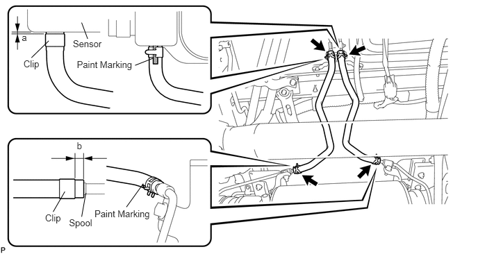
Install 2 new exhaust pipe air hoses with 4 new clips as shown in the illustration.
- Paint Marking:
Exhaust Pipe Side Vehicle Front Side Blue Vehicle Rear Side Pink Sensor Side Vehicle Front Side Yellow Vehicle Rear Side White
- Clip Position:
a 0 to 1 mm (0 to 0.039 in.) b 4 to 10 mm (0.157 to 0.394 in.)
- NOTICE:
- ·
Insert the hose on the exhaust pipe side until it comes into contact with spool.
·Insert the hose on the sensor side until it comes into contact with the sensor.
89425A
8.INSTALL NO. 2 EXHAUST GAS TEMPERATURE SENSOR
89425
9.INSTALL EXHAUST GAS TEMPERATURE SENSOR
17420K
10.INSTALL NO. 2 CENTER EXHAUST PIPE ASSEMBLY
Inspect the compression spring.
Using a vernier caliper, measure the free length of the compression spring.
- Minimum length:
38.5 mm (1.516 in.)
If the free length is less than the minimum, replace the compression spring.
Install a new gasket.
- NOTICE:
- ·
Install the gasket in the correct direction.
·Do not damage the outer surface of the gasket.
·Do not reuse the removed gasket.
·Do not push in the gasket with the No. 2 center exhaust pipe assembly when connecting it.
Install the No. 2 center exhaust pipe assembly with 4 new nuts.
- Torque:
19 N*m (194 kgf*cm, 14 ft.*lbf)
Tighten the 2 compression springs and the 2 bolts.
- Torque:
43 N*m (438 kgf*cm, 32 ft.*lbf)
17430
11.INSTALL EXHAUST TAILPIPE ASSEMBLY
Install a new gasket.
Install the exhaust tailpipe assembly with the bolt.
- Torque:
23 N*m (230 kgf*cm, 17 ft.*lbf)
Tighten 2 new nuts and the 2 bolts.
- Torque:
43 N*m (438 kgf*cm, 32 ft.*lbf)
12.INSPECT FOR EXHAUST GAS LEAK