RM2850E
_51
Engine / Hybrid System
_073293
2TR-FE STARTING
_0357011
IGNITION SWITCH
G
2TR-FE STARTING IGNITION SWITCH INSPECTION
PROCEDURE

 69570
1.INSPECT IGNITION SWITCH ASSEMBLY
a.
1.615,3.385 1.99,2.469
1.99,2.469 2.125,2.469
true
1.854,3.385 2.115,2.719
2.115,2.719 2.25,2.719
true
1.375,3.396 1.073,2.594
1.073,2.594 0.917,2.594
true
1.198,3.406 0.938,2.854
0.938,2.854 0.781,2.854
true
1.208,3.646 1,4.083
1,4.083 0.844,4.083
true
1.427,4.188 1.427,3.635
true
1.823,4.198 1.823,3.646
true
0.083,0.073 0.396,0.271
0.313,0.198
10
false
*a
1.615,0.198 1.927,0.396
0.313,0.198
10
false
*d
2.354,0.448 2.667,0.646
0.313,0.198
10
false
*e
0.896,0.448 1.208,0.646
0.313,0.198
10
false
*c
0.385,1.51 0.698,1.708
0.313,0.198
10
false
*b
2.208,2.396 2.635,2.594
0.427,0.198
10
false
ACC
2.323,2.635 2.75,2.833
0.427,0.198
10
false
ST1
0.677,2.5 1.104,2.698
0.427,0.198
10
false
IG1
0.448,2.771 0.875,2.969
0.427,0.198
10
false
AM1
1.365,4.24 1.792,4.438
0.427,0.198
10
false
IG2
0.5,4.01 0.927,4.208
0.427,0.198
10
false
AM2
1.729,4.24 2.156,4.438
0.427,0.198
10
false
ST2
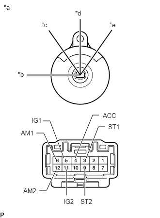
Measure the resistance according to the value(s) in the table below.
- Standard Resistance:
Tester Connection Switch Condition Specified Condition Between all terminals LOCK 10 kΩ or higher 4 (ACC) - 6 (AM1) ACC Below 1 Ω 4 (ACC) - 6 (AM1) ON Below 1 Ω 5 (IG1) - 6 (AM1) 11 (IG2) - 12 (AM2) 5 (IG1) - 6 (AM1) START Below 1 Ω 3 (ST1) - 6 (AM1) 11 (IG2) - 12 (AM2) 9 (ST2) - 12 (AM2)
| *a | Component without harness connected
(Ignition Switch Assembly) |
| *b | LOCK |
| *c | ACC |
| *d | ON |
| *e | START |
If the result is not as specified, replace the ignition switch assembly.