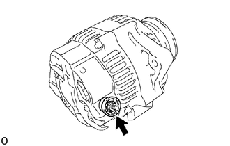
1BZ-FPE CHARGING GENERATOR REASSEMBLY
PROCEDURE

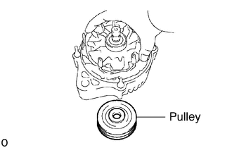
 1.PLACE DRIVE END FRAME ON PULLEY
27330
2.INSTALL ROTOR TO DRIVE END FRAME
3.INSTALL RECTIFIER END FRAME
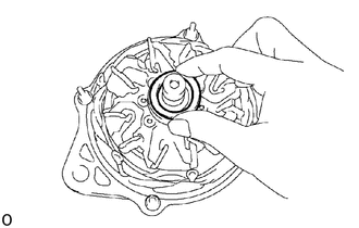
Place the alternator washer on the rotor.
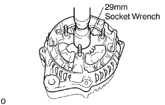
Using a 29 mm socket wrench and press, slowly press in the rectifier end frame.
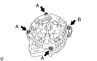
Install the cord clip and 4 nuts.
- Torque:
- Nut A:
4.5 N*m (46 kgf*cm, 40 in.*lbf)
- Nut B:
5.4 N*m (55 kgf*cm, 48 in.*lbf)
27411
4.INSTALL PULLEY
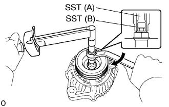
Install the pulley to the rotor shaft by tightening the pulley nut by hand.
Hold SST (A) with a torque wrench, and tighten SST (B) clockwise to the specified torque.
- SST
- 09820-63011
- Torque:
39 N*m (400 kgf*cm, 29 ft*lbf)
Check that SST (A) is secured to the pulley shaft.
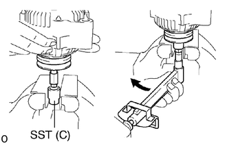
As shown in the illustration, mount SST (C) in a vise, and install the alternator to SST (C).
To torque the pulley nut, turn SST (A) in the direction shown in the illustration.
- Torque:
110.5 N*m (1,125 kgf*cm, 81 ft*lbf)
Remove the alternator from SST (C).
Turn SST (B), and remove SST (A and B).
27357
5.INSTALL RECTIFIER HOLDER
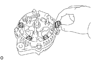
Install the 4 rubber insulators on the lead wires.
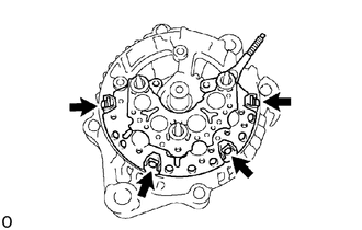
Install the rectifier holder while pushing it with the 4 screws.
- Torque:
2.94 N*m (30 kgf*cm, 26 in.*lbf)
6.INSTALL IC REGULATOR AND BRUSH HOLDER
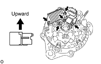
Install IC regulator and brush holder.
Place the seal plate on the rectifier end frame.
Place the IC regulator and brush holder on the rectifier end frame.
- NOTICE:
-
Be careful of the holder installation direction.
Install the 5 screws.
- Torque:
2.0 N*m ( 20 kgf*cm, 18 in.*lbf)
Place the brush holder cover on the brush holder.
7.INSTALL REAR END COVER
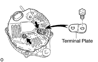
Install the rear end cover and plate terminal with the 2 nuts and screw.
- Torque:
- Bolt:
3.85 N*m (39 kgf*cm, 34 in.*lbf)
- Nuts:
4.4 N*m (45 kgf*cm, 39 in.*lbf)
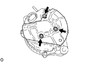
Install the rear end cover sub-assy with 3 nuts.
- Torque:
4.4 N*m ( 45 kgf*cm, 39 in.*lbf)
Install the terminal insulator with the nut.
- Torque:
4.1 N*m (41.5 kgf*cm, 36 in.*lbf)
8.CHECK THAT ROTOR ROTATES SMOOTHLY