METER / GAUGE / DISPLAY METER / GAUGE SYSTEM ON-VEHICLE INSPECTION
PROCEDURE

 1.INSPECT SPEEDOMETER
Check speedometer operation.
Using a speedometer tester, check the speedometer indication according to the table below.
- Reference: mph:
Tester Indication (mph) Acceptable Range (mph) 20 21 to 23.5 40 42 to 44.5 60 62.5 to 66.0 80 83.1 to 87.1
- Reference: km/h (w/o 100 km/h Speed Limiter):
Tester Indication (km/h) Acceptable Range (km/h) 20 21 to 25 40 41.7 to 46.2 60 62.7 to 67.2 80 83.4 to 88.4 100 104.3 to 109.3 120 125.1 to 130.6 140 145.8 to 151.8
- Reference: km/h (w/ 100 km/h Speed Limiter):
Tester Indication (km/h) Acceptable Range (km/h) 20 20.1 to 24.1 40 40.2 to 44.7 60 60.4 to 64.9 80 80.5 to 85.5 100 100.6 to 104.6 120 120.7 to 125.7 140 140.8 to 145.8
- NOTICE:
-
Tire wear, as well as overinflation or underinflation, will cause indication errors.
Check the deviation from the acceptable value of the speedometer indication.
- Reference:
Below 0.5 km/h (0.3 mph)
2.INSPECT TACHOMETER (w/ Tachometer)
Connect a tune-up test tachometer, and start the engine.
- NOTICE:
- ·
Reversing the connection of the tachometer will damage the transistors and the insides of the diodes.
·When removing or installing the tachometer, be careful not to drop or subject it to heavy shocks.
Compare the test results and the tachometer indications.
- HINT:
-
DC 13.5 V, at 25°C (77°F)
- Reference:
Standard Indication(rpm) Allowable Range(rpm)
[Data in ( ) are for reference]700 630 to 770 1000 (900 to 1100) 2000 (1850 to 2150) 3000 2800 to 3200 4000 (3800 to 4200) 5000 4800 to 5200
3.INSPECT FUEL RECEIVER GAUGE
Disconnect the g1*1 or A39*2 fuel sender gauge connector.
*1: except 1BZ-FPE
*2: for 1BZ-FPE
Turn the ignition switch to ON, and then check the position of the receiver gauge needle.
- OK:
Needle position is on EMPTY.
Connect terminals 1 and 2 on the wire harness side connector of the fuel sender gauge.
Turn the ignition switch to ON, and then check the position of the receiver gauge needle.
- OK:
Needle position is on FULL.
Reconnect the fuel sender gauge connector.
4.INSPECT FUEL LEVEL WARNING LIGHT (except 1BZ-FPE)
Disconnect the g1 fuel sender gauge connector.
Turn the ignition switch to ON, and check that the fuel level needle indicates EMPTY and that the fuel level warning light comes on.
- OK:
Fuel level warning light comes on.
Reconnect the fuel sender gauge connector.
5.INSPECT SEDIMENTER LEVEL WARNING LIGHT (for N04C)
Disconnect the A30 sedimenter level warning switch connector.
Turn the ignition switch to ON.
Connect a terminal to the other terminal of the wire harness side connector, and then check the sedimenter level warning light.
- OK:
Sedimenter level warning light comes on.
Reconnect the sedimenter level warning switch connector.
6.INSPECT FUEL FILTER CLOGGING WARNING LIGHT (for N04C)
Disconnect the A46 fuel filter clogging sensor connector.
Turn the ignition switch to ON, and check that the fuel filter clogging warning light.
- OK:
Fuel filter clogging warning light illuminates.
Reconnect the fuel filter clogging sensor connector.
7.INSPECT ENGINE COOLANT TEMPERATURE RECEIVER GAUGE (w/o Multi-information Display)
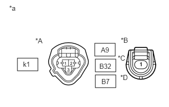
*1: for 14B
*2: for 1BZ-FPE
*3: for 1HZ
*4: for N04C, 2TR-FE
for N04C, 2TR-FE:
Disconnect the k1 engine coolant temperature sensor connector.
except N04C, 2TR-FE:
Disconnect the A9*1, B32*2 or B7*3 water temperature sender gauge connector.
Turn the ignition switch to ON, and then check the position of the receiver gauge needle.
- OK:
Needle position is on COOL.
| *A | for N04C, 2TR-FE |
| *B | for 14B |
| *C | for 1BZ-FPE |
| *D | for 1HZ |
| *a | Front view of wire harness connector
(to Engine Coolant Temperature Sensor or Water Temperature Sender Gauge) |
Connect terminals 3 (k1*4) or 1 (A9*1, B32*2, B7*3) and body ground on the wire harness side connector of the engine coolant temperature sensor.
Turn the ignition switch to ON, and then check the position of the receiver gauge needle.
- OK:
Needle position is on HOT.
Reconnect the engine coolant temperature sensor connector.
Reconnect the water temperature sender gauge connector.
8.INSPECT ENGINE OIL PRESSURE WARNING LIGHT
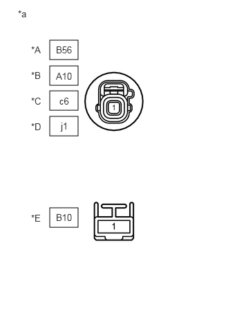
Disconnect the B56*1, A10*2, c6*3, J1*4 or B10*5 engine oil pressure switch connector.
*1: for 2TR-FE
*2: for 14B
*3: for 1BZ-FPE
*4: for N04C
*5: for 1HZ
Turn the ignition switch to ON.
Ground the terminal of the wire harness side connector, and then check the engine oil pressure warning light.
- OK:
Engine oil pressure warning light comes on.
| *A | for 2TR-FE |
| *B | for 14B |
| *C | for 1BZ-FPE |
| *D | for N04C |
| *E | for 1HZ |
| *a | Front view of wire harness connector
(to Engine Oil Pressure Switch) |
Reconnect the engine oil pressure switch connector.
9.INSPECT ENGINE OIL LEVEL WARNING LIGHT
Inspect the engine oil level warning light.
Disconnect the B56*1 or B9*2 engine oil level sensor connector from the engine oil level sensor.
*1: for 2TR-FE
*2: for N04C, 14B, 1BZ-FPE and 1HZ
Turn the ignition switch to ON.
- OK:
Engine oil level warning light comes on approximately 40 seconds after turning the ignition switch to ON.
10.INSPECT BRAKE WARNING LIGHT
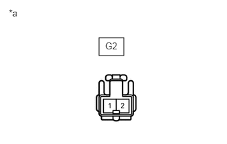
Inspect the parking brake warning light.
Disconnect the G2 parking brake switch connector.
Turn the ignition switch to ON.
Ground the terminal of the wire harness side connector, and then check the parking brake warning light.
- OK:
Brake warning light comes on.
| *a | Front view of wire harness connector
(to Parking Brake Switch) |
Reconnect the parking brake switch connector.
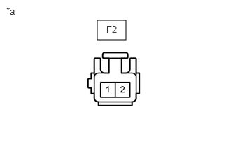
Inspect the brake fluid level warning light.
Disconnect the F2 brake fluid level warning switch connector.
Turn the ignition switch to ON.
Connect a terminal to the other terminal of the wire harness side connector, and then check the brake fluid level warning light.
- OK:
Brake warning light comes on.
| *a | Front view of wire harness connector
(to Brake Fluid Level Warning Switch) |
Reconnect the brake fluid level warning switch connector.
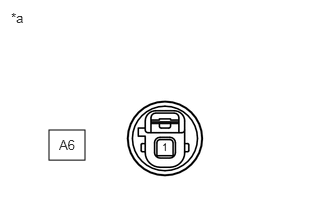
Inspect the vacuum warning light.
Disconnect the A6 vacuum warning switch connector.
Turn the ignition switch to ON.
Ground the terminal of the wire harness side connector, and then check the vacuum warning light.
- OK:
Brake warning light comes on.
| *a | Front view of wire harness connector
(to Vacuum Warning Switch) |
Reconnect the vacuum warning switch connector.
11.INSPECT BRAKE FLUID LEVEL WARNING SWITCH
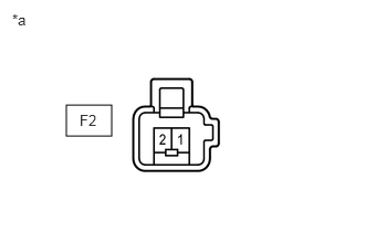
Remove the reservoir tank cap and strainer.
Disconnect the F2 brake fluid level warning switch connector.
Measure the resistance according to the value(s) in the table below.
- HINT:
-
A float is placed inside the reservoir. Its position can be changed by increasing or decreasing the brake fluid level.
- Standard Resistance:
Tester Connection Switch Condition Specified Condition 1 - 2 Float up (Switch off) 10 kΩ or higher 1 - 2 Float down (Switch on) Below 1 Ω
| *a | Component without harness connected
(Brake Fluid Level Warning Switch) |
- HINT:
-
If there is no problem after the above check is finished, adjust the brake fluid level to the MAX level.
Reconnect the brake fluid level warning switch connector.
Reinstall the reservoir tank cap and strainer.
12.INSPECT T-BELT WARNING (for 1HZ)
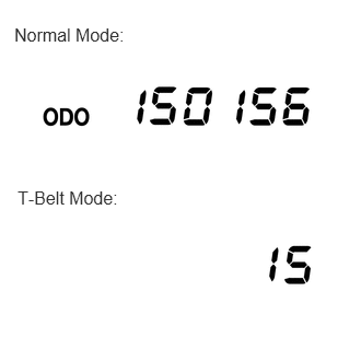
T-BELT mode display
Turn the ODO/TRIP display screen to ODO, and turn the ignition switch off.
While pressing the trip switch, turn the ignition switch to ON and hold it for 5 seconds.
Release the trip switch, then press the trip switch again within 5 seconds.
Transfer to T-BELT mode, and the following initial setting value is displayed.
- km:
15 (0,000 km)
- HINT:
-
If the meter has been replaced before, the displayed value might not be the initial setting value.
Rewriting replacement setting value
Press the trip switch and rewrite the replacement setting value.
| Condition | Setting Value |
|---|---|
| When a belt is replaced | km: 15 (0,000 km) |
| When a meter is replaced | km: 15 (150000 km) - (Kilometrage when the meter is replaced.) |
- HINT:
-
When pressing the trip switch, the displayed value is changed to 1 (0,000 km) for the first time and after this, increases in increments of 1 (0,000 km) up to 20 (0,000 km). If switch operation is not performed for more than 30 seconds, the setting value will not be changed, the display screen turns to "ODO", and the mode returns to the normal mode.
T-BELT mode completion
- NOTICE:
-
If T-BELT mode is completed, even though belt replacement or meter replacement has not been performed, the T-BELT warning is reset.
After setting the replacement setting value, hold the trip switch on for more than 5 seconds, then release the trip switch.
Check that the display has changed to "ODO" and that the warning light has gone off.
13.INSPECT DPF WARNING LIGHT (for N04C-UH)
Disconnect the J2 and A52 connectors.
Measure the resistance according to the value(s) in the table below.
- Standard Resistance:
Tester Connection Condition Specified Condition J2-4 (DPNR) - A54-10 (W2) Always Below 1 Ω J2-4 (DPNR) - Body ground Always 10 kΩ or higher
- HINT:
-
If the result is not as specified, repair or replace the harness or connector.
Remove the combination meter assembly.
Reconnect the J2 connector.
Measure the voltage according to the value(s) in the table below.
- Standard voltage:
Tester Connection Switch Condition Specified Condition J2-4 (DPNR) - Body ground Ignition switch ON, DPF switch pressed Below 1 V
(DPF warning light comes on)
- HINT:
-
If the result is not as specified, replace the combination meter assembly.