DRIVE SHAFT / PROPELLER SHAFT PROPELLER SHAFT ASSEMBLY DISASSEMBLY
PROCEDURE

 1.REMOVE SPIDER BEARING
- HINT:
-
Use the same procedure for all propeller shaft universal joint spider bearing.
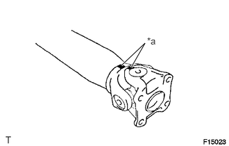
Place matchmarks on the flange yoke and the propeller shaft.
| *a | Matchmark |
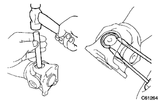
Using a brass bar and hammer, slightly tap in the spider bearings.
Using 2 screwdrivers, remove the 4 snap rings from the grooves.
Fix the propeller shaft in a vise between aluminum plates.
- NOTICE:
-
Do not overtighten the vise.
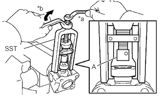
Using SST, remove the spider bearing from the propeller shaft.
| *a | Hold |
| *b | Turn |
- SST
- 09332-25010
- NOTICE:
-
Apply a small amount of grease to the threads of SST (center bolt) before use.
- HINT:
-
Before installing SST, sufficiently raise the part labeled A. If the part labeled A is too low, it may be difficult to install SST.
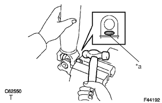
Clamp the spider bearing in a vise between aluminum plates and tap off the propeller shaft with a hammer.
| *a | Hammering Point |
- NOTICE:
- ·
Do not overtighten the vise.
·Do not tap the shaft.
- HINT:
-
Remove the spider bearing on the opposite side using the same procedure.
Install the 2 removed spider bearings to the universal joint spider.
Fix the universal joint spider in a vise between aluminum plates.
- NOTICE:
-
Do not overtighten the vise.
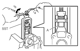
Using SST, remove the spider bearing from the flange yoke.
| *a | Hold |
| *b | Turn |
- SST
- 09332-25010
- NOTICE:
-
Apply a small amount of grease to the threads of SST (center bolt) before use.
- HINT:
-
Before installing SST, sufficiently raise the part labeled A. If the part labeled A is too low, it may be difficult to install SST.
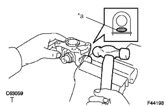
Clamp the spider bearing in a vise between aluminum plates and tap off the flange yoke with a hammer.
| *a | Hammering Point |
- NOTICE:
-
Do not overtighten the vise.
- HINT:
-
Remove the spider bearing on the opposite side using the same procedure.
Remove the universal joint spider.
2.REMOVE CENTER NO. 1 SUPPORT BEARING ASSEMBLY
Fix the flange in a vise between aluminum plates.
- NOTICE:
-
Do not overtighten the vise.
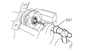
Using SST and a hammer, loosen the staked part of the nut.
- SST
- 09930-00010
- NOTICE:
- ·
Be sure to use SST with the tapered end facing the propeller shaft.
·Do not grind SST tip with a grinder, etc.
·Loosen the staked part of the nut completely, otherwise the threads of the propeller shaft may be damaged.
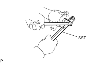
Using SST and a socket wrench 30 mm, hold the flange and remove the nut and washer.
- SST
- 09330-00021
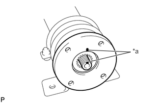
Place matchmarks on the flange and the propeller shaft.
| *a | Matchmark |
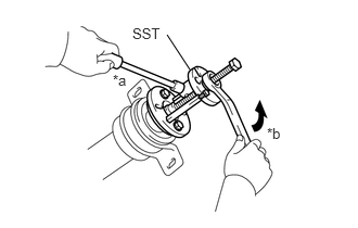
Using SST, remove the flange.
| *a | Hold |
| *b | Turn |
- SST
- 09950-30012 (09951-03010, 09953-03010, 09954-03010, 09955-03030, 09956-03030)
- NOTICE:
-
Apply a small amount of grease to the threads of SST (center bolt) before use.
Remove the center No. 1 support bearing assembly from the propeller shaft.
3.REMOVE NO. 2 PROPELLER SHAFT DUST DEFLECTOR
Fix the center No. 1 support bearing assembly in a vise between aluminum plates.
- NOTICE:
-
Do not overtighten the vise.
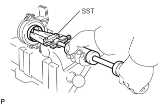
Using SST, remove the 2 No. 2 propeller shaft dust deflectors.
- SST
- 09308-00010
4.REMOVE NO. 3 PROPELLER SHAFT DUST DEFLECTOR
Remove the No. 3 propeller shaft dust deflector from the center No. 1 support bearing assembly.
5.REMOVE NO. 4 PROPELLER SHAFT DUST DEFLECTOR
Remove the No. 4 propeller shaft dust deflector from the center No. 1 support bearing assembly.
6.REMOVE CENTER NO. 1 SUPPORT BEARING
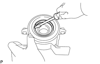
Using a screwdriver, remove the 2 center support bearing snap rings.
Fix the center No. 1 support bearing assembly in a vise between aluminum plates.
- NOTICE:
-
Do not overtighten the vise.
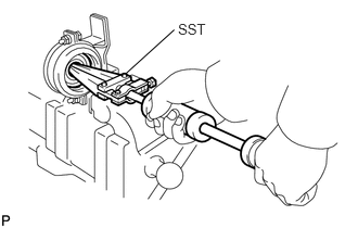
Using SST, remove the center No. 1 support bearing.
- SST
- 09308-00010
7.REMOVE CENTER NO. 1 SUPPORT BEARING CUSHION SUB-ASSEMBLY
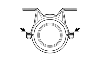
Remove the 2 bolts, 2 nuts and 2 washers, and separate the center No. 1 and No. 2 support bearing housings.
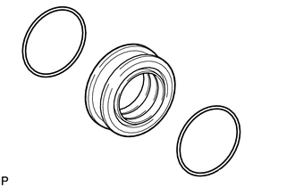
Remove the 2 center support bearing cushion set rings from the center No. 1 support bearing cushion sub-assembly.
8.REMOVE CENTER NO. 2 SUPPORT BEARING ASSEMBLY
- HINT:
-
Use the same procedure as for the center No. 1 support bearing assembly.
9.REMOVE NO. 6 PROPELLER SHAFT DUST DEFLECTOR
- HINT:
-
Use the same procedure as for the No. 2 propeller shaft dust deflector.
10.REMOVE NO. 7 PROPELLER SHAFT DUST DEFLECTOR
- HINT:
-
Use the same procedure as for the No. 3 propeller shaft dust deflector.
11.REMOVE NO. 8 PROPELLER SHAFT DUST DEFLECTOR
- HINT:
-
Use the same procedure as for the No. 4 propeller shaft dust deflector.
12.REMOVE CENTER NO. 2 SUPPORT BEARING
- HINT:
-
Use the same procedure as for the center No. 1 support bearing.
13.REMOVE CENTER NO. 2 SUPPORT BEARING CUSHION SUB-ASSEMBLY
- HINT:
-
Use the same procedure as for the center No. 1 support bearing cushion sub-assembly.