DRIVE SHAFT / PROPELLER SHAFT PROPELLER SHAFT ASSEMBLY INSPECTION
PROCEDURE

 1.INSPECT PROPELLER SHAFT ASSEMBLY
Check the propeller shaft tube for wear or damage.
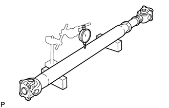
Set the propeller shaft assembly on V-blocks. Using a dial indicator, measure the runout of the center of the propeller shaft assembly.
- Maximum runout:
0.8 mm (0.0314 in.)
If the runout is greater than the maximum, replace the propeller shaft assembly.
2.INSPECT UNIVERSAL JOINT SPIDER ASSEMBLY
Fix the propeller shaft assembly in a vise between aluminum plates.
- NOTICE:
-
Do not overtighten the vise.
Check the universal joint spider assembly for wear or damage.
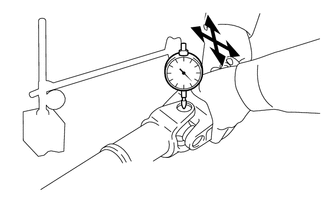
Using a dial indicator, measure the spider bearing axial play.
- Standard axial play:
0.05 mm (0.00196 in.) or less
If the axial play is not as specified, replace the universal joint spider and the spider bearing.
3.INSPECT CENTER SUPPORT BEARING ASSEMBLY
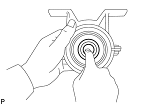
Check that the center support bearing assembly rotates smoothly when the bearing is rotated by hand and check if there are any cracks or damage.
If there are any malfunctions, replace the center support bearing.