DRIVE SHAFT / PROPELLER SHAFT PROPELLER SHAFT ASSEMBLY REASSEMBLY
PROCEDURE

 1.INSTALL SPIDER BEARING
- HINT:
-
Use the same procedure for all propeller shaft universal joint spider bearing.
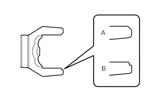
Select 4 new spider bearings according to the shape of the yoke end.
| Type | Identification Paint |
|---|---|
| A | None |
| B | White |
Install the grease fitting to a new universal joint spider.
- Torque:
6.4 N*m (65 kgf*cm, 57 in.*lbf)
- NOTICE:
-
When replacing the spider bearing, be sure that the grease fitting hole is facing to the direction shown in the illustration.
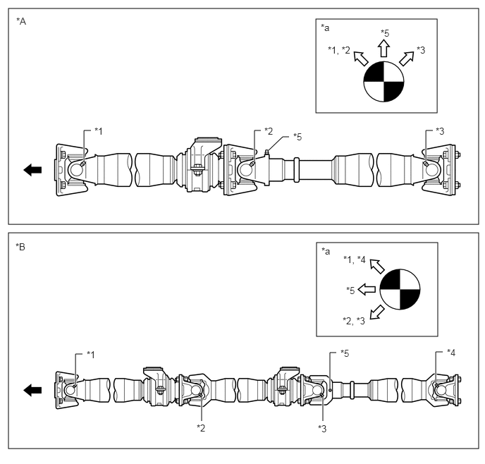
| *A | for Short Wheelbase | *B | for Long Wheelbase |
| *1 | No. 1 Universal Joint Grease Fitting | *2 | No. 2 Universal Joint Grease Fitting |
| *3 | No. 3 Universal Joint Grease Fitting | *4 | No. 4 Universal Joint Grease Fitting |
| *5 | Sleeve Yoke Grease Fitting | - | - |
| *a | This illustration shows the directions of the grease fitting as seen from the rear. | - | - |

|
Front of the Vehicle | - | - |
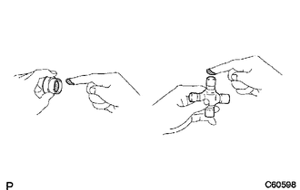
Apply MP grease to the universal joint spider and the 4 spider bearings.
Fix the flange yoke in a vise between aluminum plates.
- NOTICE:
-
Do not overtighten the vise.
Install the universal joint spider to the flange yoke.
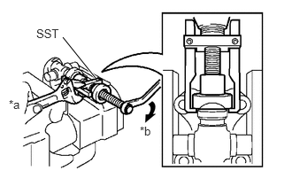
Using SST, install the spider bearing to the flange yoke.
| *a | Hold |
| *b | Turn |
- SST
- 09332-25010
- NOTICE:
-
Apply a small amount of grease to the threads of SST (center bolt) before use.
- HINT:
-
Install the spider bearing on the opposite side using the same procedure.
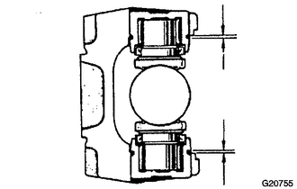
Using SST, adjust both spider bearings so that the snap ring grooves are at maximum and equal width.
- SST
- 09332-25010
Install 2 new snap rings of equal thickness which will allow standard axial play.
- Standard axial play:
0.05 mm (0.00196 in.) or less
| Part No. | Mark | Thickness |
|---|---|---|
| 90520-29024 | - | 1.985 to 2.015 mm (0.0782 to 0.0793 in.) |
| 90520-29025 | Light brown | 2.015 to 2.045 mm (0.0794 to 0.0805 in.) |
| 90520-29026 | Blue | 2.045 to 2.075 mm (0.0806 to 0.0816 in.) |
| 90520-29027 | - | 2.075 to 2.105 mm (0.0817 to 0.0828 in.) |
| 90520-29039 | 1 | 1.98 to 2.00 mm ( 0.0780 to 0.0787 in.) |
| 90520-29040 | 2 | 2.00 to 2.02 mm ( 0.0788 to 0.0795 in.) |
| 90520-29041 | 3 | 2.02 to 2.04 mm ( 0.0796 to 0.0803 in.) |
| 90520-29042 | 4 | 2.04 to 2.06 mm ( 0.0804 to 0.0811 in.) |
| 90520-29043 | 5 | 2.06 to 2.08 mm ( 0.0812 to 0.0818 in.) |
| 90520-29044 | 6 | 2.08 to 2.10 mm ( 0.0819 to 0.0826 in.) |
| 90520-29045 | 7 | 2.10 to 2.12 mm ( 0.0827 to 0.0834 in.) |
| 90520-29046 | 8 | 2.12 to 2.14 mm ( 0.0835 to 0.0842 in.) |
| 90520-29047 | 
|
2.14 to 2.16 mm ( 0.0843 to 0.0850 in.) |
| 90520-29048 | 10 | 2.16 to 2.18 mm ( 0.0851 to 0.0858 in.) |
- NOTICE:
-
Use the snap rings with as close to the same thickness as possible on both ends.
Using a hammer, tap the flange yoke until there is no clearance between the spider bearing and the snap ring.
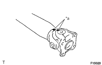
Align the matchmarks on the flange yoke and the propeller shaft.
| *a | Matchmark |
Install the spider bearing to the propeller shaft.
- HINT:
-
Install the spider bearing on the propeller shaft side using the procedure described above.
2.INSTALL CENTER NO. 1 SUPPORT BEARING CUSHION SUB-ASSEMBLY
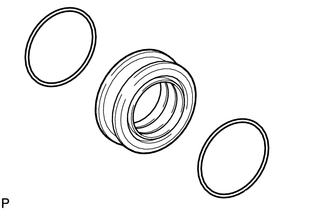
Install the 2 center support bearing cushion set rings to the center No. 1 support bearing cushion sub-assembly.
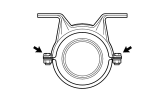
Install the No. 1 and No. 2 center support bearing housings with the 2 bolts, 2 nuts and 2 washers.
- Torque:
25 N*m (251 kgf*cm, 18 ft.*lbf)
3.INSTALL CENTER NO. 1 SUPPORT BEARING
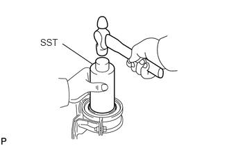
Using SST, install the center No. 1 support bearing.
- SST
- 09226-10010
Install the 2 center support bearing snap rings to the center No. 1 support bearing assembly.
4.INSTALL NO. 4 PROPELLER SHAFT DUST DEFLECTOR
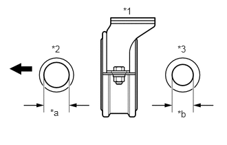
Install the No. 4 propeller shaft dust deflector to the center No. 1 support bearing assembly as shown in the illustration.
| *1 | Center No. 1 Support Bearing Assembly |
| *2 | No. 3 Propeller Shaft Dust Deflector |
| *3 | No. 4 Propeller Shaft Dust Deflector |
| *a | 32.5 mm (1.280 in.) |
| *b | 28.5 mm (1.122 in.) |
|
|
Front of the Vehicle |
5.INSTALL NO. 3 PROPELLER SHAFT DUST DEFLECTOR
- HINT:
-
See the procedure for the No. 4 propeller shaft dust deflector.
6.INSTALL NO. 2 PROPELLER SHAFT DUST DEFLECTOR
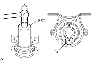
Using SST, install the 2 No. 2 propeller shaft dust deflectors.
| *a | Water Drain Hole |
- SST
- 09226-10010
- NOTICE:
-
Face the water drain hole toward the bottom.
7.INSTALL CENTER NO. 1 SUPPORT BEARING ASSEMBLY
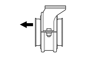
Install the center No. 1 support bearing assembly to the propeller shaft as shown in the illustration.
|
|
Front of the Vehicle |
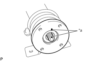
Align matchmarks on the flange and the propeller shaft.
| *a | Matchmark |
Temporarily install a washer and new nut.
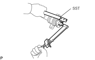
Using SST and a socket wrench 30 mm, hold the flange and fully tighten the nut.
- SST
- 09330-00021
- Torque:
167 N*m (1700 kgf*cm, 123 ft.*lbf)
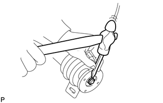
Using a chisel and hammer, stake the nut.
8.INSTALL CENTER NO. 2 SUPPORT BEARING CUSHION SUB-ASSEMBLY
- HINT:
-
Use the same procedure as for the center No. 1 support bearing cushion sub-assembly.
9.INSTALL CENTER NO. 2 SUPPORT BEARING
- HINT:
-
Use the same procedure as for the center No. 1 support bearing.
10.INSTALL NO. 8 PROPELLER SHAFT DUST DEFLECTOR
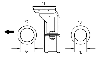
Install the No. 8 propeller shaft dust deflector to the center No. 2 support bearing assembly as shown in the illustration.
| *1 | Center No. 2 Support Bearing Assembly |
| *2 | No. 7 Propeller Shaft Dust Deflector |
| *3 | No. 8 Propeller Shaft Dust Deflector |
| *a | 32.5 mm (1.280 in.) |
| *b | 28.5 mm (1.122 in.) |
|
|
Front of the Vehicle |
11.INSTALL NO. 7 PROPELLER SHAFT DUST DEFLECTOR
- HINT:
-
See the procedure for the No. 8 propeller shaft dust deflector.
12.INSTALL NO. 6 PROPELLER SHAFT DUST DEFLECTOR
- HINT:
-
Use the same procedure as for the No. 2 propeller shaft dust deflector.
13.INSTALL CENTER NO. 2 SUPPORT BEARING ASSEMBLY
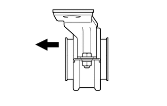
Install the center No. 2 support bearing assembly to the propeller shaft as shown in the illustration.
|
|
Front of the Vehicle |
Align matchmarks on the flange and the propeller shaft.
| *a | Matchmark |
Temporarily install a washer and new nut.
Using SST and a socket wrench 30 mm, hold the flange and fully tighten the nut.
- Torque:
167 N*m (1700 kgf*cm, 123 ft.*lbf)
Using a chisel and hammer, stake the nut.