DRIVE SHAFT / PROPELLER SHAFT PROPELLER SHAFT ASSEMBLY INSTALLATION
CAUTION / NOTICE / HINT
- NOTICE:
-
When replacing the propeller shaft, be sure that each universal joint and grease fitting hole is facing to the direction shown in the illustration.
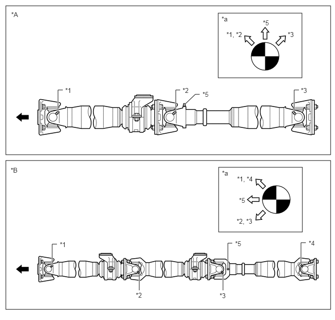 0.125,0.125 7.073,3.313 6.948,3.188 0.125,3.438 7.073,6.625 6.948,3.188 4.677,3.583 6.469,4.969 1.792,1.385 4.667,0.281 6.458,1.667 1.792,1.385 1.24,2.385 1.24,1.927 1.24,1.927 1.344,1.927 true 1.115,5.688 1.115,5.229 1.115,5.229 1.219,5.229 true 6.438,5.656 6.438,5.198 6.438,5.198 6.542,5.198 true 4.875,5.74 4.875,5.208 4.875,5.208 4.969,5.208 true 3.76,2.385 3.76,1.927 3.76,1.927 3.854,1.927 true 6.292,2.385 6.292,1.927 6.292,1.927 6.396,1.927 true 3.969,2.219 4.177,2.021 4.177,2.021 4.271,2.021 false 2.979,5.865 2.979,6.219 true 4.771,5.865 4.771,6.219 true 1.396,1.854 1.792,2.104 0.396,0.25 10 false *1 4.844,0.656 5.333,0.99 0.49,0.333 10 false *1, *2 5.073,3.75 5.74,4.063 0.667,0.313 10 false *1, *4 5.063,4.656 5.792,5.031 0.729,0.375 10 false *2, *3 0.24,0.229 0.771,0.635 0.531,0.406 10 false *A 0.229,3.563 0.781,4.021 0.552,0.458 10 false *B 1.281,5.156 1.729,5.438 0.448,0.281 10 false *1 6.604,5.125 7.073,5.469 0.469,0.344 10 false *4 5.031,5.135 5.438,5.375 0.406,0.24 10 false *5 5.115,4.208 5.521,4.5 0.406,0.292 10 false *5 3.906,1.854 4.354,2.156 0.448,0.302 10 false *2 6.438,1.854 6.906,2.177 0.469,0.323 10 false *3 6.156,0.656 6.563,0.979 0.406,0.323 10 false *3 4.333,1.938 4.688,2.271 0.354,0.333 10 false *5 5.625,0.406 6,0.781 0.375,0.375 10 false *5 4.74,0.323 5.188,0.667 0.448,0.344 10 false *a 4.75,3.625 5.135,3.906 0.385,0.281 10 false *a 2.906,6.24 3.313,6.521 0.406,0.281 10 false *2 4.698,6.25 5.115,6.469 0.417,0.219 10 false *3
Text in Illustration *A for Short Wheelbase *B for Long Wheelbase *1 No. 1 Universal Joint Grease Fitting *2 No. 2 Universal Joint Grease Fitting *3 No. 3 Universal Joint Grease Fitting *4 No. 4 Universal Joint Grease Fitting *5 Sleeve Yoke Grease Fitting - - *a This illustration shows the directions of the grease fitting as seen from the rear. - - 
Front of the Vehicle - -
PROCEDURE

 1.INSTALL FRONT PROPELLER SHAFT ASSEMBLY (except Short Wheelbase)
Completely remove any oil or the like and clean the contact surfaces of the front propeller shaft flange and the parking brake drum sub-assembly.
Align the matchmarks on the front propeller shaft flange and the parking brake drum sub-assembly.
Install the 4 nuts and 4 washers.
- Torque:
96 N*m (979 kgf*cm, 71 ft.*lbf)
Temporarily install the front propeller shaft assembly with the 2 nuts, 2 bolts and 2 collars.
2.INSTALL CENTER PROPELLER SHAFT ASSEMBLY (for Short Wheelbase)
Completely remove any oil or the like and clean the contact surfaces of the center propeller shaft flange and the parking brake drum sub-assembly.
Align the matchmarks on the center propeller shaft flange and the parking brake drum sub-assembly.
Install the 4 nuts and 4 washers.
- Torque:
96 N*m (979 kgf*cm, 71 ft.*lbf)
Temporarily install the center propeller shaft assembly with the 2 nuts, 2 bolts and 2 collars.
3.INSTALL CENTER PROPELLER SHAFT ASSEMBLY (except Short Wheelbase)
Completely remove any oil or the like and clean the contact surfaces of the center propeller shaft flange and the front propeller shaft flange.
Align the matchmarks on the center propeller shaft flange and the front propeller shaft flange.
Install the 4 nuts, 4 bolts and 4 washers.
- Torque:
96 N*m (979 kgf*cm, 71 ft.*lbf)
Temporarily install the center propeller shaft assembly with the 2 nuts, 2 bolts and 2 collars.
4.INSTALL REAR PROPELLER SHAFT ASSEMBLY
Completely remove any oil or the like and clean the contact surfaces of the rear propeller shaft flange and the center propeller shaft flange.
Align the matchmarks on the rear propeller shaft flange and the center propeller shaft flange.
Install the 4 nuts, 4 bolts and 4 washers.
- Torque:
96 N*m (979 kgf*cm, 71 ft.*lbf)
Completely remove any oil or the like and clean the contact surfaces of the rear propeller shaft flange and the rear differential companion flange.
Align the matchmarks on the rear propeller shaft flange and the rear differential companion flange.
Install the 4 nuts, 4 bolts and 4 washers.
- Torque:
96 N*m (979 kgf*cm, 71 ft.*lbf)
5.ADJUST CENTER SUPPORT BEARING ASSEMBLY
With the vehicle unloaded, adjust and fully tighten the center support bearing assembly so that the cushion rubber of the center support bearing assembly is equal before and behind the housing.
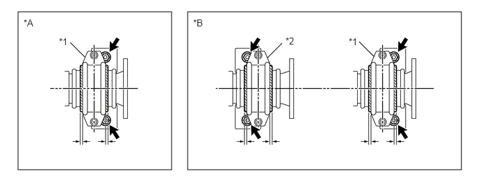
| *A | for Short Wheelbase | *B | for Long Wheelbase |
| *1 | Center No. 1 Support Bearing Assembly | *2 | Center No. 2 Support Bearing Assembly |
- Torque:
37 N*m (377 kgf*cm, 27 ft.*lbf)
- NOTICE:
-
After installation, check that the center of the housing is at a right angle to the propeller shaft axis.