14B ENGINE MECHANICAL CYLINDER HEAD CYLINDER HEAD COMPONENTS INSPECTION AND REPAIR
PROCEDURE

 1.CLEAN TOP SURFACES OF PISTONS AND CYLINDER BLOCK
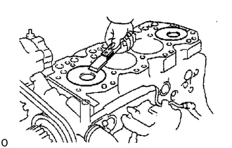
Turn the crankshaft, and bring each piston to the top dead center (TDC). Using a gasket scraper, remove all the carbon from the piston top surface.
Remove all the gasket material from the top of the cylinder block.
- NOTICE:
-
Be careful not to scratch the surfaces.
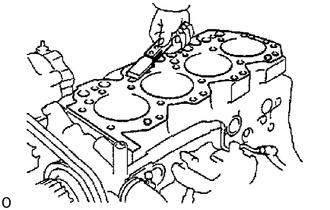
Using compressed air, blow carbon and oil from the bolt holes.
- CAUTION:
-
Protect your eyes when using high-compressed air.
2.CLEAN CYLINDER HEAD
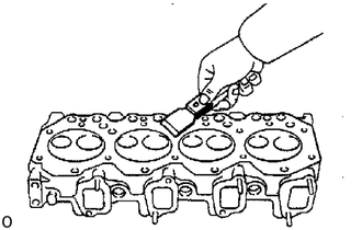
Remove gasket material
Using a gasket scraper, remove all the gasket material from the cylinder block contact surface.
- NOTICE:
-
Be careful not to scratch the cylinder block contact surface.
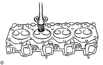
Clean intake and exhaust ports
Using a wire brush, remove all the carbon from the intake and exhaust ports.
- NOTICE:
-
Be careful not to scratch the valve contact surface.
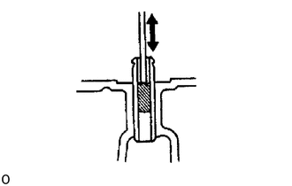
Clean valve guide bushings
Using a valve guide bushing brush and solvent, clean all the guide bushings.
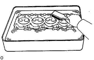
Clean cylinder head
Using a soft brush and solvent, thoroughly clean the cylinder head.
3.INSPECT CYLINDER HEAD
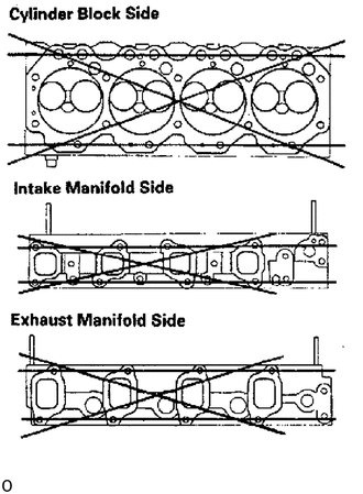
Inspect for flatness
Using a precision straight edge and feeler gauge, measure the surfaces contacting the cylinder block and the manifolds for warpage.
- Maximum warpage:
0.20 mm (0.0079 in.)
If warpage is greater than maximum, replace the cylinder head.
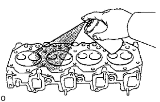
Inspect for cracks
Using a dye penetrant. check the intake ports, exhaust ports and surface contacting the cylinder block.
If cracked, replace the cylinder head.
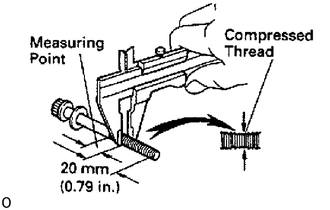
Inspect cylinder head bolts
Using vernier calipers, measure the minimum outer diameter of the compressed thread at the measuring point.
- Standard outer diameter:
11.800 - 12.000 mm (0.4646 - 0.4724 in.)
- Minimum outer diameter:
11.60 mm (0.4567 in.)
If the outer diameter is less than minimum, replace the bolt.
4.CLEAN VALVES
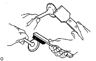
Using a gasket scraper, chip off any carbon from the valve head.
Using a wire brush, thoroughly clean the valve.
5.INSPECT VALVE STEMS AND GUIDE BUSHINGS
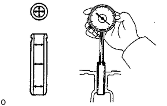
Using a caliper gauge, measure the inside diameter of the guide bushing.
- Bushing inside diameter:
9.010 - 9.030 mm (0.3547 - 0.3555 in.)
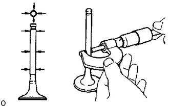
Using a micrometer, measure the diameter of the valve stem.
- Valve stem diameter:
Intake
8.968 - 8.984 mm (0.3531 - 0.3537 in.)
Exhaust
8.954 - 8.970 mm (0.3525 - 0.3531 in.)
Subtract the valve stem diameter measurement from the guide bushing inside diameter measurement.
- Standard oil clearance:
Intake
0.026 - 0.062 mm (0.0010 - 0.0024 in.)
Exhaust
0.040 - 0.076 mm (0.0016 - 0.0030 in.)
- Maximum oil clearance:
Intake
0.10 mm (0.0039 in.)
Exhaust
0.12 mm (0.0047 in.)
If the clearance is greater than maximum, replace the valve and guide bushing.
6.IF NECESSARY, REPLACE VALVE GUIDE BUSHING
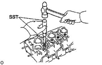
Using SST and a hammer, tap out the valve guide bushing.
- SST
- 09201-10000 (09201-01080)
09950-70010 (09951-07100)
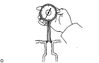
Using a caliper gauge, measure the bushing bore diameter of the cylinder head.
If the bushing bore diameter of cylinder head is more than 14.018 mm (0.5519 in.), replace the cylinder head.
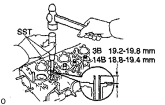
Using SST and a hammer, drive in a new valve guide bushing to where there is 19.2 - 19.8 mm (0.756 - 0.780 in.) or 18.8 - 19.4 mm (0.740 - 0.756 in.) protruding from the cylinder head.
- SST
- 09201-10000 (09201-01080)
09950-70010 (09951-07100)
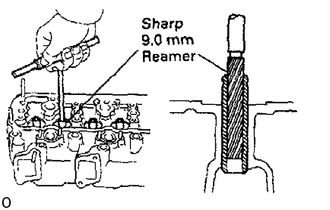
Using a sharp 9.0 mm reamer, ream the valve guide bushing to obtain the standard specified clearance (See step 5 above) between the valve guide bushing and new valve stem.
7.INSPECT AND GRIND VALVES
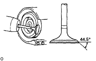
Grind the valve only enough to remove pits and carbon.
Check that the valve is ground to the correct valve face angle.
- Valve face angle:
44.5°
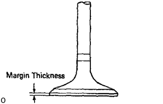
Check the valve head margin thickness.
- Standard margin thickness:
Intake
1.4 mm (0.055 in.)
Exhaust
3B: 1.8 mm (0.071 in.)
14B: 1.7 mm (0.067 in.)
- Minimum margin thickness:
Intake
0.9 mm (0.035 in.)
Exhaust
3B: 1.3 mm (0.051 in.)
14B: 1.2 mm (0.047 In.)
If the margin thickness is less than minimum, replace the valve.
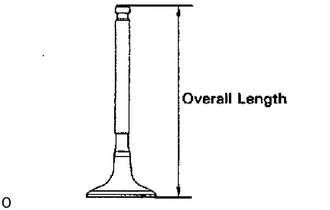
Check the valve overall length.
- Standard overall length:
Intake
126.35 - 126.75 mm (4.9744 - 4.9902 in.)
Exhaust
3B: 126.35 - 126.75 mm (4.9724 - 4.9902 in.)
14B: 126.22 - 126.62 mm (4.9693 - 4.9850 in.)
- Minimum overall length:
Intake
126.05 mm (4.9626 in.)
Exhaust
3B: 126.05 mm (4.9626 in.)
14B: 125.92 mm (4.9575 in.)
If the overall length is less than minimum, replace the valve.
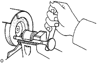
Check the surface of the valve stem tip for wear.
If the valve stem tip is worn, resurface the tip with a grinder or replace the valve.
- NOTICE:
-
Do not grind off more than minimum.
8.INSPECT AND CLEAN VALVE SEATS
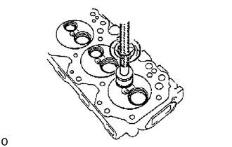
Using a 45° carbide cutter, resurface the valve seats.
Remove only enough metal to clean the seats.
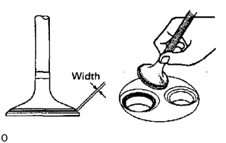
Check the valve seating position.
Apply a light coat of prussian blue (or white lead) to the valve face. Lightly press the valve against the seat. Do not rotate valve.
Check the valve face and seat for the following:
If blue appears 360° around the valve face, the valve is concentric. If not, replace the valve.
If blue appears 360° around the valve seat, the guide and face are concentric. If not, resurface the seat.
Check that the seat contact is in the middle of the valve face with the following width:
1.9 - 2.3 mm (0.075 - 0.091 in.)
If not, correct the valve seats as follows:
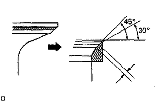
If the seating is too high on the valve face, use 30° and 45° cutters to correct the seat.
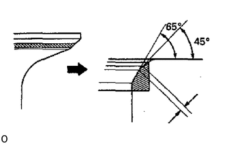
If the seating is too low on the valve face, use 65° and 45° cutters to correct the seat.
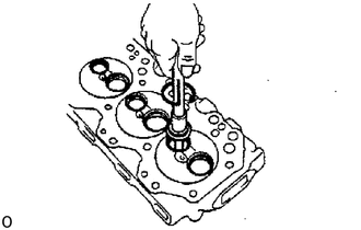
Hand-lap the valve and valve seat with an abrasive compound.
After hand-lapping, clean the valve and valve seat.
9.INSPECT VALVE SPRINGS
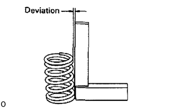
Using a steel square, measure the deviation of the valve spring.
- Maximum deviation:
2.0 mm (0.079 in.)
If the deviation is greater than maximum, replace the valve spring.
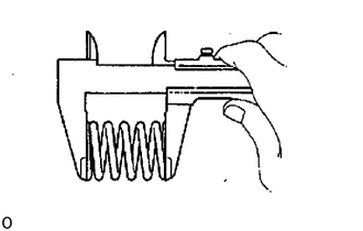
Using vernier calipers, measure the free length of the valve spring.
- Free length:
Inner spring
43.21 - 45.28 mm (1.7012 - 1.7827 in.)
Outer spring
48.70 - 50.73 mm (1.9173 - 1.9973 in.)
If the free length is not as specified, replace the valve spring.
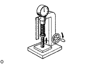
Using a spring tester, measure the tension of the valve spring at the specified installed length.
- Installed tension:
Inner spring
96 - 135 N (9.8 - 13.8 kgf, 21.6 - 30.4 lbf) at 38.19 mm (1.5035 in.)
Outer spring
215 - 277 N (21.9 - 28.3 kgf, 48.3 - 62.4 lbf) at 41.69 mm (1.6413 in.)
If the installed tension is not as specified, replace the valve spring.
10.INSPECT VALVE ROCKER ARM AND SHAFT
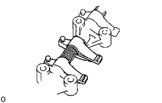
Check the pad valve bridge contacting surface of the rocker arm for wear.
If the pad valve bridge contact surface is worn, disassemble and replace the rocker arm.
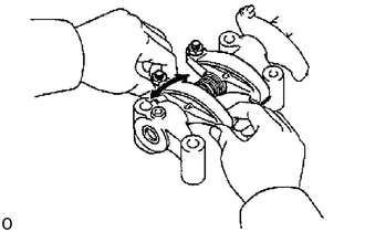
Check that each rocker arm turns smoothly.
If movement is felt, disassemble and check the oil clearance.
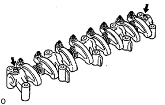
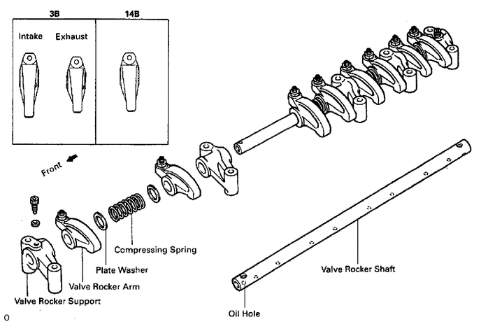
Using a 5 mm hexagon wrench, remove the 2 bolts and washers, and disassemble the parts.
- HINT:
-
Arrange the disassembled parts in correct order.
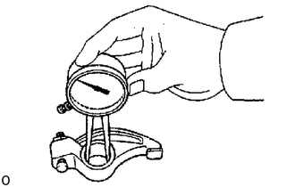
Using a caliper gauge, measure the inside diameter of the rocker arm.
- Rocker arm Inside diameter:
18.512 - 18.533 mm (0.7288 - 0.7296 in.)
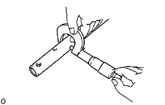
Using a micrometer, measure the diameter of the rocker arm shaft.
- Shaft diameter:
18.472 - 18.493 mm (0.7272 - 0.7281 in.)
Subtract the rocker arm shaft measurement from the rocker arm measurement.
- Standard oil clearance:
0.019 - 0.061 mm (0.0007 - 0.0024 in.)
- Maximum oil clearance:
0.10 mm (0.0039 in.)
If the clearance is greater than maximum. replace the rocker shaft and shaft.
Assemble the parts as shown in the illustration.
11.INSPECT PUSH RODS
Place the push rod on V-blocks.
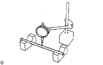
Using a dial indicator, measure the circle runout at the center of the push rod.
- Maximum circle runout:
0.50 mm (0.0197 in.)
If the circle runout is greater than maximum, replace the push rod.
12.INSPECT INTAKE AND EXHAUST MANIFOLDS
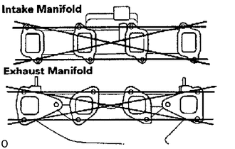
Using a precision straight edge and feeler gauge, measure the surface contacting the cylinder head for warpage.
- Maximum warpage:
0.20 mm (0.0079 in.)
If warpage is greater than maximum, replace the manifold.