14B FUEL FUEL INJECTION PUMP INJECTION PUMP COMPONENTS INSPECTION
PROCEDURE

 1.INSPECT DELIVERY VALVES
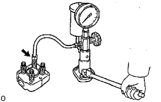
w/ CPV:
Attach the nozzle tester to the delivery valve holder of the pipe you wish to measure.
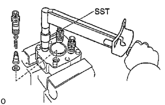
Use the nozzle tester to check the valve opening pressure of the delivery valve.
- Standard valve opening pressure:
7,350 - 8,330 kPa
(75 - 85 kgf/ cm2, 1,067 - 1,209 psi)
If the valve opening pressure of the delivery valve is not within specification, replace the delivery valve assembly.
- SST
- 09260-54012 (09269-54020)
- Torque:
59 N*m (600 kgf*cm, 43 ft.*lbf)
- NOTICE:
-
Do not lose the steel ball when doing an overhaul.
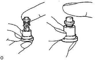
w/o CPV:
- NOTICE:
-
Do not touch the sliding surfaces of the pump plunger and delivery valves.
Pull up the valve and close the hole at the valve seat bottom end with your thumb.
When the valve is released, it should sink down quickly and stop at the position where the relief ring closes the valve seat hole.
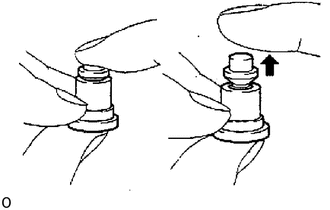
Close the hole at the valve seat bottom end with your thumb.
Insert the valve into the valve seat and press down with your finger. When your finger is released, the valve should rise back to its original position.
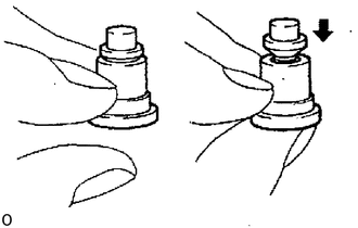
Remove your thumb from the valve seat hole.
The valve should close completely by its own weight.
If operation is not as specified, replace the valve as a set.
- HINT:
-
Before using a new valve set, wash off the rust prevention compound with light oil or gasoline. Then re-wash with diesel fuel and perform the above tests.
2.INSPECT PUMP PLUNGER, SPILL RING AND DISTRIBUTIVE HEAD
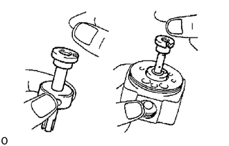
Tilt the spill ring (distributive head) slightly and pull out the plunger.
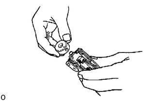
When released, the plunger should sink down smoothly into the spill ring (distributive head) by its own weight.
Rotate the plunger and repeat the test at various positions.
If the plunger sticks at any position, replace the parts as a set.
- NOTICE:
-
Do not touch the sliding surface of the pump plunger.
Insert the governor link ball pin into the spill ring and check that it moves smoothly without any play.
3.INSPECT PLUNGER SPRINGS FOR DEVIATION
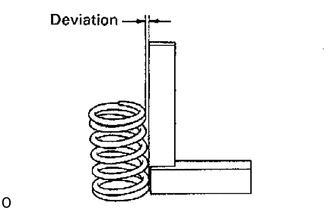
Using a steel square, check the deviation of the plunger springs.
- Maximum deviation:
2.0 mm (0.079 in.)
If deviation is greater than maximum, replace both springs.
4.INSPECT SPRING LENGTH
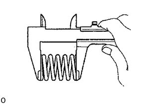
Using vernier calipers, measure the free length of each spring.
Spring free length:
- Delivery valve spring:
- 15B-F, 15B-FT:
12.6 mm (0.496 in.)
- Others:
19.4 mm (0.764 in.)
- Plunger spring:
- 15B-F, 15B-FT:
34.1 mm (1.343 in.)
- Others:
32.4 mm (1.276 in.)
- Coupling spring:
- 3B, 14B:
15.4 mm (0.606 in.)
- Boost compensator spring:
- 15B-FT:
19.9 mm (0.783 in.)
If the free length is not as specified, replace the spring(s).
5.INSPECT ROLLER RING AND ROLLERS
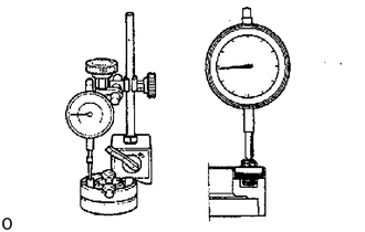
Using a dial indicator, measure the roller height.
- Maximum roller height variation:
0.02 mm (0.0008 in.)
If the variation is greater than specification, replace the roller ring and roller as a set.
6.INSPECT FUEL CUT SOLENOID
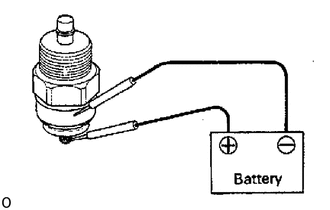
Connect the solenoid valve body and terminal to the battery terminals.
You should feel the click from the solenoid valve when the battery power is connected and disconnected.
If the solenoid valve is not operating properly, replace it.
7.INSPECT PICKUP SENSOR
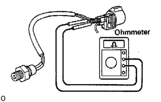
Using an ohmmeter, measure the resistance between the terminals.
- Resistance:
650 - 970 Ω
If resistance is not as specified, replace the sensor.
8. IF NECESSARY, REPLACE OIL SEAL
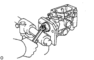
Using a wrench, pry out the oil seal.
- NOTICE:
-
Be careful not to damage to the pump body.
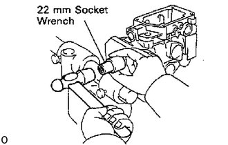
Apply MP grease to the lip of a new oil seal.
Using a 22 mm socket wrench, tap in the oil seal until its surface is flush with the pump housing.