A861E AUTOMATIC TRANSMISSION / TRANSAXLE AUTOMATIC TRANSMISSION SYSTEM Stop Light Switch Circuit
DESCRIPTION
The purpose of this circuit is to prevent the engine from stalling while driving in the lock-up condition when brakes are suddenly applied. When the brake pedal is depressed, this switch sends a signal to the transmission control ECU assembly. Then the transmission control ECU assembly cancels the operation of the lock-up clutch while braking is in progress.
WIRING DIAGRAM
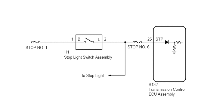
CAUTION / NOTICE / HINT
- NOTICE:
-
Inspect the fuses for circuits related to this system before performing the following inspection procedure.
PROCEDURE
Check that the stop light comes on when the brake pedal is depressed, and goes off when the brake pedal is released.
- OK:
Stop light switch function is normal.
- Result:
Proceed to OK NG
OK
NG
Connect the GTS to the DLC3.
Turn the ignition switch to ON.
Turn the GTS on.
Enter the following menus: Powertrain / ECT / Data List.
Accordance to the display on the GTS, read the Data List.
| Tester Display | Measurement Item | Range | Normal Condition | Diagnostic Note |
|---|---|---|---|---|
| Stop Light Switch | Stop light switch status | OFF or ON | ·
OFF: Brake pedal is released ·
ON: Brake pedal is depressed |
- |
- Result:
Result Proceed to Data display is within Normal Condition range A Data display is not within Normal Condition range B
A
B
Disconnect the transmission control ECU assembly connectors.
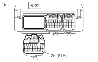
| *a | Rear view of wire harness connector
(to Transmission Control ECU Assembly) |
Measure the voltage according to the value(s) in the table below.
- Standard Voltage:
Tester Connection Condition Specified Condition B132-25 (STP) - Body ground Stop light switch on
(Brake pedal depressed)11 to 14 V Stop light switch off
(Brake pedal released)Below 1 V
- HINT:
-
If there is a short in the STP terminal circuit, there may be a malfunction in the circuit of a connected ECU.
- Result:
Proceed to OK NG
OK
NG