A861E AUTOMATIC TRANSMISSION / TRANSAXLE FLOOR SHIFT ASSEMBLY DISASSEMBLY
PROCEDURE

 33504F
1.REMOVE SHIFT LEVER KNOB SUB-ASSEMBLY
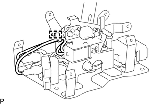
Detach the clamp to disconnect the wire harness.
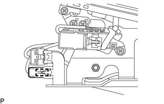
Disconnect the transmission control switch connector from the shift lever plate.
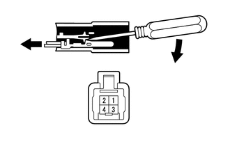
Using a screwdriver, disconnect the 2 and 4 terminals from the transmission control switch connector.
- NOTICE:
-
Do not disconnect the 1 and 3 terminals.
- HINT:
-
Place a mark on one side of the wire harness to identify the original terminal positions.
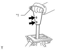
| *1 | Shift Lever Knob Button |
Remove the 2 screws, and then while pressing the shift lever knob button by hand, remove the shift lever knob sub-assembly.
Remove the shift lever knob button and shift lever knob button compression spring from the shift lever knob sub-assembly.
84722
2.REMOVE TRANSMISSION CONTROL SWITCH
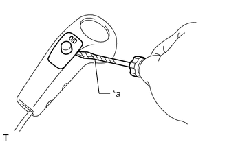
| *a | Protective Tape |
Using a screwdriver with its tip wrapped with protective tape, remove the transmission control switch from the shift lever knob sub-assembly.
- HINT:
-
Tape the screwdriver tip before use.
35974
3.REMOVE LOWER POSITION INDICATOR HOUSING
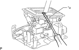
| *a | Protective Tape |
Using a screwdriver with its tip wrapped with protective tape, remove the shift lock release button cover.
- HINT:
-
Tape the screwdriver tip before use.
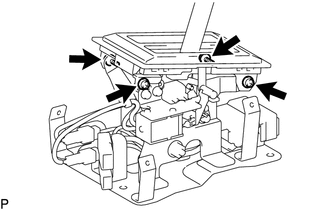
Remove the 4 screws and lower position indicator housing from the shift lever plate.
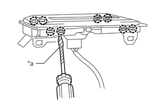
| *a | Protective Tape |
Using a screwdriver with its tip wrapped with protective tape, detach the 8 clamps and remove the upper position indicator housing.
- HINT:
-
Tape the screwdriver tip before use.
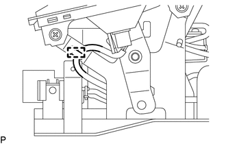
Detach the clamp and disconnect the indicator light wire.
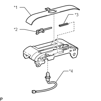
| *1 | Position Indicator Slide Cover |
| *2 | Shift Lock Release Link |
| *3 | Shift Lock Release Link Compression Spring |
| *4 | Indicator Light Wire |
Remove the position indicator slide cover, shift lock release link, shift lock release link compression spring and indicator light wire from the lower position indicator housing.
Remove the bulb from the indicator light wire.
33058
4.REMOVE SHIFT LOCK SOLENOID BRACKET SUB-ASSEMBLY
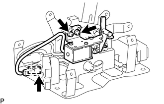
Disconnect the shift lock control ECU connector from the shift lock solenoid connector.
Detach the clamp and disconnect the shift lock solenoid connector from the shift lever plate.
Remove the 2 screws and shift lock solenoid bracket sub-assembly.
84727
5.REMOVE SHIFT LOCK CONTROL SWITCH
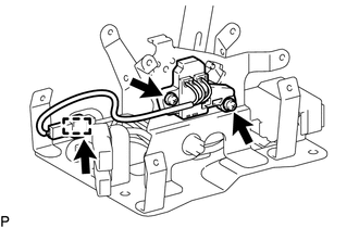
Disconnect the shift lock control ECU connector from the shift lock control switch connector.
Detach the clamp and disconnect the shift lock control switch connector from the shift lever plate.
Remove the 2 screws and shift lock control switch.
33054
6.REMOVE NO. 2 FLOOR SHIFT LEVER SUB-ASSEMBLY
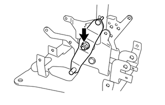
Remove the nut, washer, control shaft bush and No. 2 floor shift lever sub-assembly from the shift lever plate.
33503F
7.REMOVE FLOOR SHIFT SHIFT LEVER SUB-ASSEMBLY
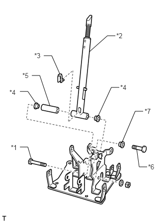
| *1 | Floor Shift Control Shaft |
| *2 | Floor Shift Shift Lever Sub-assembly |
| *3 | No. 2 Shift Lever Wire Guide |
| *4 | Shift Lever Bush |
| *5 | Shift Lever Collar |
| *6 | Floor Shift Control Link Shaft |
| *7 | Control Shaft Bush |
Remove the nut, washer, floor shift control shaft and floor shift shift lever sub-assembly from the shift lever plate.
Remove the No. 2 shift lever wire guide, 2 shift lever bushes and shift lever collar from the floor shift shift lever sub-assembly.
Remove the floor shift control link shaft and control shaft bush from the shift lever plate.
85933
8.REMOVE SHIFT LOCK CONTROL ECU
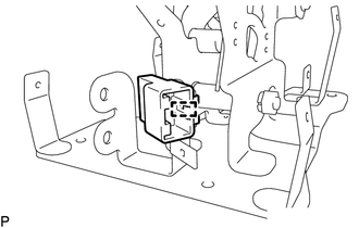
Detach the clamp and disconnect the shift lock control ECU connector from the shift lever plate.
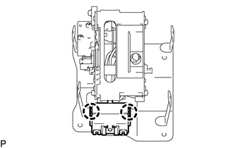
Detach the 2 claws and remove the shift lock control ECU from the shift lever plate.
33625
9.REMOVE SHIFT LEVER KNOB SLEEVE
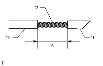
| *1 | Shift Lever Knob Sleeve |
| *2 | Detent Rod Compression Spring |
| *3 | Floor Shift Shift Lever Sub-assembly |
Measure dimension A from the bottom of the shift lever knob sleeve to the top of the floor shift shift lever sub-assembly.
- HINT:
-
The measured dimension A is used as a standard when installing.
Remove the shift lever knob sleeve and detent rod compression spring.
33631
10.REMOVE DETENT ROD
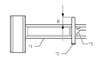
| *1 | Floor Shift Shift Lever Sub-assembly |
| *2 | Detent Rod Grooved Pin |
| *3 | Detent Rod |
Measure dimension B from the edge of the floor shift shift lever sub-assembly to the end of the detent rod grooved pin.
- HINT:
-
The measured dimension B is used as a standard when installing.
Using a pin punch, tap out the detent rod grooved pin.
Remove the detent rod and No. 1 shift lever wire guide.